ARTICLE 13: SAFETY STRUCTURES AND HOMOLOGATION
- General Principles
- The purpose of this Article is to define the safety structures of the car and all the homologation processes necessary to guarantee that each car that is eligible to race satisfies all the relevant requirements.
- Should a fundamental weakness or sub-optimal level of safety become evident in either the definition of the structures or the homologation procedures, the FIA retains the right to modify the relevant regulations without observing the deadlines otherwise dictated by the prevailing governance regulations. In any case, such actions will be discussed in the Technical Advisory Committee.
- All impact tests must be carried out in accordance with FIA Test Procedure 01/00 (same as current one), in the presence of an FIA technical delegate and by using measuring equipment which has been calibrated to the satisfaction of the FIA technical delegate.
- Any significant modification introduced into any of the structures tested shall require that part to pass a further test.
- With the exception of tests described in point 3, all static and dynamic load tests must be performed with the secondary roll structure (whether dummy or otherwise) removed.
- All homologation tests on the survival cell will be carried out before the Zylon panels have been fitted.
- Survival Cell Frontal Impact Test
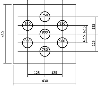
A 50mm (+/-1mm) thick aluminium plate should be attached to the front bulkhead of the survival cell through the mounting points of the frontal impact absorbing structure. The plate should:- Measure 430mm (+/-1mm) wide x 430mm (+/-1mm) high.
- Be fitted symmetrically about the car centre plane.
- Be fitted in a vertical sense in order to ensure force distribution is similar to that with the nose fitted.
- Have seven M10 x 30mm holes in the outer face arranged in a grid pattern as shown in the diagram below. The test laboratory will then fit a 5mm thick 430mm x 430mm steel plate to these holes using a 5mm washer stack.
All parts which could materially affect the outcome of the test must be fitted to the test structure which must be solidly fixed to the trolley through its engine mounting points but not in such a way as to increase its impact resistance.
The fuel tank must be fitted and must be full of water.
A dummy weighing at least 75kg must be fitted with safety belts described in Article 12.5.6 fastened. However, with the safety belts unfastened, the dummy must be able to move forwards freely in the cockpit. The dummy shall be equipped with a helmet to FIA8860 or FIA8859 and an FHR to FIA8858 (the mass of the helmet and FHR should be recorded, but should not be included in the 75kg). The safety belts shall be fastened to represent in-race conditions.
The fire extinguishers must also be fitted.
For the purposes of this test, the total mass of the trolley and test structure shall be between 900kg and 925kg and the velocity of impact not less than 15 metres/second.
The impact wall must be fitted with seven carbon composite crush tubes which develop a combined 500kN nominal load as follows (picture at the end of the article):- 2 x tubes, 900mm long, from T-zero to T-end, directed into the lower left and right M10 attachment points.
- 1 x tube, 800mm long, from T-100mm to T-end, directed into the central M10 attachment point.
- 2 x tubes, 750mm long, from T-150mm to T-end, directed into the central upper and lower M10 attachment points.
- 2 x tubes, 650mm long, from T-250mm to T-end, directed into the upper left and right M10 attachment points.
The resistance of the test structure must be such that following the impact there is no damage to the survival cell or to the mountings of the safety belts or fire extinguishers.
The maximum deceleration in the chest of the dummy for a cumulative 3ms shall be reported, this being the resultant of data from the three orthogonal axes.
The minimum chassis acceleration from T=30ms is 52g.
The maximum chassis displacement from T=Zero is 425mm.
- Roll Structure Testing
- The principal roll structure must be subjected to the following static test:
- Rubber 3mm thick may be used between the load pads and the roll structure.
- The peak load must be applied in less than three minutes and be maintained for 10 seconds.
- Under the load, deformation must be less than 25mm when measured along the loading axis and any structural failure limited to 100mm below the top of the roll structure when measured vertically.
- A load equivalent to 60kN laterally, 70kN longitudinally in a rearward direction and 105kN vertically, must be applied to the top of the structure through a rigid flat pad which is 200mm in diameter and perpendicular to the loading axis.
- During the test, the roll structure must be attached to the survival cell which is supported on its underside on a flat plate, fixed to it through its engine mounting points and wedged laterally by any of the static load test pads desribed in following articles.
- The secondary roll structure attachments must be subjected to the following two static tests. For each test:
- Rubber 3mm thick may be used between the load pads and the roll structure
- A secondary roll structure amust be fitted.
- The loads shall be applied using a 150mm diameter flat, rigid pad whose centre lies in the specified loading position. The pad shall have only one translational degree of freedom, this being along the axis of load application.
- For each test, peak loads must be applied in less than three minutes and be maintained for five seconds.
- After five seconds of application, there must be no failure of any part of the survival cell or of any attachment between the structure and the survival cell.
- Centreline Test
A load equivalent 130.1kN vertically downward and51.6kN longitudinally rearward must be applied at a position [Xc -785, 0, 830]. in one of the following two ways:- A physical test to 100% of the test load (140kN); or
- A physical test to 57% of the test load (80kN) plus detailed calculations to show that the attachments are able to sustain more than 120% of the test load (168kN) when fitted with the secondary structure and with the deformation simulated as elastic.
- The methodology for the calculations shall be authenticated with data from the physical test prescribed above for the load range from 0kN to 80kN. The load and displacement shall be recorded along the axis of load application together with the vertical displacement of the three attachments.
During the test, the structure must be attached to the survival cell which is supported on its underside on a flat plate, fixed to it through its engine mounting points and, optionally, through the front bulkhead and/or the mountings of the lower side impact structures.
- Lateral Test
- A load equivalent to 104.5kN laterally inward and 93.2kN longitudinally rearward must be applied to the outer surface of the structure at a position [Xc -590, 233.5, 810]. in one of following two ways:
- A physical test to 100% of the test load (140kN); or
- A physical test to 71% of the test load (100kN) plus detailed calculations to show that the attachments are able to sustain more than 120%of the test load (168kN) when fitted with the secondary structure and with the deformation simulated as elastic.
The methodology for the calculations shall be authenticated with data from the physical test prescribed above for the load range from 0kN to 50kN. The load and displacement shall be recorded along the axis of load application together with the lateral displacement of the three attachments.
During the test, the survival cell should be fixed at its rear bulkhead via its engine mounts to a strongwall and supported along its lower face by a surface plate.
The survival cell may be restrained laterally and vertically at its front end by a cradle that wraps around all four sides of the survival cell. This cradle may extend as far forward as the plane A-A, but may not extend further rearwards than XA=600.
The side of the survival cell that is opposite to the application point of the Halo test load may be restrained laterally by supports that conform to the sides of the survival cell. These lateral supports may not extend further forward than XC= -1075 or above Z=545.
- In addition to the static load tests described above, each team must supply detailed calculations which clearly show that:
- The survival cell will sustain a load of 75kN vertically upward on each rear attachment of the Secondary Roll Structure.
- The survival cell and bracket will sustain a load equivalent to 99kN vertically upward and 99kN longitudinally rearward on the axis of the front attachment of the Secondary Roll Structure.
- The Principal Roll Structure will sustain the test the article above with the longitudinal component in a forward direction.
- A load equivalent to 104.5kN laterally inward and 93.2kN longitudinally rearward must be applied to the outer surface of the structure at a position [Xc -590, 233.5, 810]. in one of following two ways:
- The principal roll structure must be subjected to the following static test:
- Survival Cell Load Tests
- Conditions applicable to all static load tests
- All tests described above must be carried out on every survival cell intended for use. During these tests (on deflections greater than 3.0mm), the deflection across the inner surfaces must not exceed 120% of the deflection obtained on the survival cell, before Zylon panels are applied.
- Deflections and deformations will be measured at the centre of area of the load pad unless otherwise stated.
- All peak loads must be applied in less than three minutes, through a ball jointed junction at the centre of area of the pad and maintained for 30 seconds.
- All tests must be carried out by using measuring equipment which has been calibrated to the satisfaction of the FIA technical d.
- A radius of 3mm is permissible on the edges of all load pads and rubber 3mm thick may be placed between them and the test structure.
- the survival cells must always be produced in an identical condition in order that their mass may be compared. If the mass differs by more than 5% from the one subjected to the impact test, the test must be repeated.
- Any significant modification introduced into any of the structures tested shall require that part to pass a further test.
- The Survival cell may be mounted in any orientation provided that the mounting arrangement does not increase the strength or stiffness of the survival cell being tested.
- Survival cell fuel tank side test
Pads of diameter 200mm, which conform to the shape of the survival cell, must be placed against the outermost sides of the survival cell with the centre of the pad 150mm above the lowest part of the survival cell at that section. The centre of these pads will coincide, in the longitudinal direction, with an X-plane passing through the centroid of the fuel tank. The technical delegate may select however to alter the longitudinal position for this test if he considers the above criterion to not correspond to the weakest position of the survival cell side in the area of the fuel tank.
A constant transverse horizontal load of 50kN will be applied and, under the load, there must be no structural failure of the inner or outer surfaces of the survival cell.
Deflections and deformations will be measured at the centre of the pad.
Permanent deformation must be less than 1.0mm after the load has been released for 1 minute. - Survival cell wheel contact side test
Pads 200mm in diameter which conform to the shape of the survival cell, must be placed against the outermost sides of the survival cell. The centre of these pads must lie:- In the X- direction, on an X-plane passing through the rearmost point at which the outer end of the forward-most front wheel tether would make contact with the survival cell when swung about the inner attachment.
- In the Z-direction, at the mid-point of the height of the structure at that section.
- A constant transverse horizontal load of 40kN will be applied to the pads and, under the load, there must be no structural failure of the inner or outer surfaces of the survival cell and the total deflection must not exceed 15mm.
Permanent deformation must be less than 1.0mm after the load has been released for 1 minute.
- Survival cell floor test
A pad of 200mm diameter must be placed on the survival cell floor, in a position determined by the FIA technical delegate, and corresponding to the fuel tank. A vertical upwards load of 25kN will be applied.
Under the load, there must be no structural failure of the inner or outer surfaces of the survival cell.
Permanent deformation must be less than 0.5mm after the load has been released for 1 minute. - Cockpit floor test
A pad of 200mm diameter must be placed beneath the survival cell, and a vertical upwards load of 30kNapplied.
Under the load, there must be no structural failure of the inner or outer surfaces of the survival cell.
Permanent deformation must be less than 0.5mm after the load has been released for 1 minute. - Cockpit rim tests
Two pads, each of which is 50mm in diameter, must be placed on both sides of the cockpit rim with their upper edges at the same height as the top of the cockpit side with their centres.
A constant transverse horizontal load of 50kN will then be applied at 90° to the car centre plane and, under the load, deformation must be less than 10mm when measured along the loading axis and there must be no structural failure of the inner or outer surfaces of the survival cell.
Permanent deformation must be less than 1.0mm after the load has been released for 1 minute. - Cockpit Side Test 1
A 225mm diameter pad which conforms to the shape of the survival cell at the load application point, must be placed against the outermost sides of the survival cell At the Competitor’s discretion, a load of either [0, 200, 0]kN or [48.6, 194, 0]kN shall be applied through a ball joint and, under the load, there must be no structural failure of the inner or outer surfaces of the survival cell and the total deflection must not exceed 15mm.
The load and displacement shall be recorded along the axis of load application.
Permanent deformation must be less than 5mm after the load has been released for 1 minute.
Chassis conditions should be exactly the same as all other tests. - Cockpit Side Test 2
A 225mm diameter pad which conforms to the shape of the survival cell at the load application point, must be placed against the outermost sides of the survival cell, centred.
At the Competitor’s discretion, a load of either [0, 300, 0]kN or [72.9, 291, 0]kN shall be applied through a ball joint and, under the load, there must be no structural failure of the inner or outer surfaces of the survival cell and the total deflection must not exceed 30mm. The load and displacement shall be recorded along the axis of load application.
After 5 seconds of application, there must be no failure of the survival cell.
Chassis conditions should be exactly the same as all other tests.
In addition to the physical test, the team shall provide detailed calculations to show that the cockpit side is able to sustain a lateral load of 380kN applied at the following 6 positions.
The methodology for the calculations shall be authenticated by comparing data from the physical test for the load range from 0kN to 275kN and the calculated case. - Nose Push-off Test
During this test, the survival cell must be resting on a flat plate and secured to it solidly but not in a way that could increase the strength of the attachments being tested. A dummy front impact structure may be used for this test.
The 250mm of the dummy structure closest to the survival cell should be identical in design and construction to the ones used for all other tests. The dummy structure should not in any way increase the strength of the survival cell or of the attachment between the survival cell and the impact structure.
A constant transversal horizontal load of 66.7kN must be applied to one side of the impact structure and at the mid-point of the height of the structure in the other tests.
All loads must be applied through a ball-jointed junction at the centre of area of the pad.
After 30 seconds of application, there must be no failure of the survival cell or of any attachment between the structure and the survival cell. Additionally, teams must supply calculations that show that there would be no failure of the survival cell or of any attachment between the structure and the survival cell if a load of 83kN were applied XA= -750 through the dummy structure. - Engine Separation
It must be demonstrated by calculation that in the case of an accident that causes the engine to become separated from the survival cell, significant structural failure of the survival cell does not occur.
The survival cell should be restrained ahead of the seatback bulkhead. A load of [FX, FY, MZ] = K.[-1N, 5N, 3Nm], acting through and about [XPU=0, 0, 210], should be applied to the survival cell through the engine mounts using a representative engine. K should be increased up to the first engine mount failure. The analysis should be repeated, disconnecting the failed fixing until only two engine fixings remain. In all cases, the failure should remain local to the engine mounts and there should be no significant exposure of the fuel cell. - Forward Survival Cell Test
A rigid pad measuring 200mm in X and 320mm in Y which has a single degree of freedom along the direction of loading, must be placed against the outer surface of the survival cell.
The load axis must lie:- On the Y=0 plane.
- In a position between the front of the survival cell and XC=-1600, determined by the technical delegate and communicated to the team two weeks before the homologation.
- Normal to the surface of the survival cell.
- A constant load of 30kN will be applied and, under the load, there must be no structural failure of the inner or outer surfaces of the survival cell and the deflection must be less than 5mm.
A cradle may be used on the opposite side of the survival cell to react the load.
- Conditions applicable to all static load tests
- Side Impact Structure
- Side Impact Structure Specification
Two impact absorbing structures must be fitted on each side of the survival cell and must be solidly attached to it. The purpose of these structures is to protect the driver in the event of a lateral impact and, in order to ensure this is the case, strength tests of the mountings must be carried out successfully.
The impact absorbing structures must be manufactured and mounted to the survival cell in accordance with the following specifications:- The structures must be mounted with the principal axes of their prismatic mounting sections perpendicular to the longitudinal and vertical centre plane of the car, and with an incidence (defined as the angle between the major axis and Z=0) of 00 for the upper structure and within the range of 00 and -100 (nose up) for the lower structure.
The centres of area of their outermost longitudinal vertical cross sections must be positioned longitudinally, vertically and laterally at specific locations depending on the car lenght. - The two side impact structures must be fully enclosed by bodywork, and hence no part of them should be exposed to the external air stream.
- Mountings must be permanently bonded to the structures to enable them to be attached to the survival cell; each of them must:
- Incorporate a closed end and internal abutment to the impact structure that must be capable of withstanding the lateral load described in this article without a structural contribution from the bonded interface.
- Lie entirely inboard of a plane which lies 292mm inboard of the outermost longitudinal vertical cross section of the impact structure.
- Be arranged in order that the outermost surface created by an interface between the mounting and structure lies on a vertical surface that is located between the plane defined point 2 above and a vertical plane which intersects the leading and trailing edges of the structure no more than 357mm and 332mm inboard of the outermost longitudinal vertical cross section of the impact structure respectively.
- Be arranged in order that the innermost extent of the bonded interface between the mounting and structure is offset inboard by a minimum of 44mm from the vertical surface defined in 3 above.
- Be arranged in order that the bonded interface covers the entire external area of the structure between the innermost and outermost extents defined in 3 and 4 above.
- To allow for debris compaction, the internal volumes of the structures must be empty outboard of vertical planes which:
- For the upper structure, intersects the leading, and trailing edges of the structure at least 342mm inboard of the outermost longitudinal vertical cross section of the impact structure. Furthermore, the projected area of the structure onto a Z-Plane, between this plane and the plane defined in 3.3 aboce must be greater than 7440mm2.
- For the lower structure, intersects the leading, and trailing edges of the structure at least 357mm inboard of the outermost longitudinal vertical cross section of the impact structure. Furthermore, the projected area of the structure onto a Z-Plane, between this plane and the plane defined in 3.3 above must be greater than 9225mm2.
- No parts which would prevent proper function of the impact structures in the event of a lateral impact may be:
- The construction of any of the components is such that they would not, cause significant damage to the survival cell in the event of a lateral impact.
- Components of the oil and coolant systems and charge air cooling, electrical units and pneumatic pressure vessels are no closer than 20mm at any point to the closest impact structure.
- Electrical units and pneumatic vessels.
- Have a total volume that does not exceed 2 litres on each side of the survival cell.
- Have an individual assembly density of no more than 1500 kg/m3.
- Are orientated such that corners or edges are not likely to cause significant damage to the survival cell in the event of a lateral impact.
- The structures must be mounted with the principal axes of their prismatic mounting sections perpendicular to the longitudinal and vertical centre plane of the car, and with an incidence (defined as the angle between the major axis and Z=0) of 00 for the upper structure and within the range of 00 and -100 (nose up) for the lower structure.
- Side impact structure push-off calculations
Each team must supply detailed calculations which clearly show that the mountings of the upper and lower side impact structures are capable of withstanding:- Horizontal loads of 40kN and 60kN applied simultaneously to the upper and lower structures respectively in a rearward direction through ball-jointed pads, which may conform to the shape of the structures, measuring 100mm high x 100mm wide and whose centre of area lies 100mm inboard of the centre of the outermost longitudinal vertical cross-section of the impact structure.
- Horizontal loads of 40kN and 60kN applied simultaneously to the upper and lower structures respectively in a forward direction through ball-jointed pads, which may conform to the shape of the structures, measuring 100mm high x 100mm wide and whose centre of area lies 100mm inboard of the centre of the outermost longitudinal vertical cross-section of the impact structure.
- A vertical load of 35kN applied in an upward direction to the lower impact structure through a ball-jointed pad, which may conform to the shape of the structure, measuring 200mm long x 100mm wide whose centre of area lies 100mm inboard of the centre of the outermost longitudinal vertical cross section of the impact structure.
- A vertical load of 27kN applied in a downward direction to the upper impact structure through a ball-jointed pad, which may conform to the shape of the structure, measuring 200mm long x 100mm wide whose centre of area lies 100mm inboard of the centre of the outermost longitudinal vertical cross section of the impact structure.
- In all cases, the calculations should show that there will be no structural failure of the parts. It should be assumed that ball-jointed pads are used, the joint lying at the centre of area of the pad.
- Side impact structure push-off tests
These tests may be carried out on any survival cell.
The tests may be performed on either side of the survival cell.
During the push off tests the survival cell must be resting on a flat plate and secured to it solidly but not in a way that could increase the strength of the attachments being tested.
Dummy test parts may be used in place of the impact structure provided the test part incorporates identical mounting details to those described above and does not in any way increase the strength of the attachments being tested.
During the first test rearward horizontal loads of 40kN and 60kN must be applied simultaneously to the upper and lower structures respectively through ball joints or ball-jointed pads whose centre of area lies 100mm inboard of the centre of the outermost cross-section of the dummy impact structures.
During the second test an upward vertical load of 35kN must then be applied to the lower impact absorbing structure using a ball joint or a ball-jointed pad whose centre of area lies 100mm inboard of the centre of the outermost cross section of the dummy lower impact structure.
After five seconds of application there must be no failure of any structures or of any attachment between the structure and the survival cell. - Side impact structure squeeze tests
These tests may be carried out on any survival cell.
The tests may be performed on either side of the survival cell.
During the test, the survival cell may be supported in any way provided this does not increase the strength of the attachments being tested.
Dummy test parts may be used in place of the impact structure provided the test parts incorporate identical mounting details to those described above and do not in any way increase the strength of the attachments being tested.
Loads of 100kN and 150kN must be applied simultaneously to the dummy upper and lower structures respectively in a lateral direction using a hemispherical pad or ball joint, loading through the centre cross section, 292mm from the outermost longitudinal vertical cross-section of both impact structures.
After five seconds of application, there must be no failure of the survival cell or the attachments between the structures and the survival cell.
Each team must supply detailed calculations which clearly show that the mountings of the upper and lower side impact structures satisfy the requirement 13.5.1 above.
- Side Impact Structure Specification
- Front Impact Structure
- Front Impact Structure Specification
An impact absorbing structure must be fitted in front of the survival cell. This structure need not be an integral part of the survival cell but must be solidly attached to it and be arranged symmetrically about the car centre plane.
The impact absorbing structure must affix to the survival cell using a minimum of four attachments having the same nominal strength.
Its forward-most point must be forward of XF= -1150. The X-planes D-D and E-E are defined as respectively 50mm and 150mm behind this forward-most point.
This structure, excluding fairings or removable wing, must have:- A single external vertical cross-section at the plane D-D. The area of the part of this section that lies less than 100mm from Y=0 must exceed 9000mm2.
- A single external vertical cross-section whose area exceeds 20000mm2 at the plane E-E.
- Ahead of the plane D-D, no part above Z=235.
- Behind the plane D-D, no part above a plane normal to Y=0 and containing points [Y, Z] [0, 235] in plane D-D and [0, 305] in plane E-E.
- Each external X-plane cross-section between E-E and XA= -100, must be a single section with an area which exceeds a value given by a linear taper from 20000mm2 to 60000mm2 respectively.
- Behind an X-plane 100mm behind E-E, with the exception of bodywork joggles, any normal to the external surface of the Impact structure must not subtend an angle greater than 25° to an X-plane.
- All lines drawn normally and externally to a cross-section taken at XA= -100 must not cross the car centre plane.
- Once the requirements of a-g have been met, minimal apertures may be applied for mechanical components or sensors.
- Any bodywork ahead of the plane defined in 4 above, and above Z=235, and less than 166mm from the centre plane must be constructed of laminate PL-LWT-FAIRING.
- Front Impact Structure Push-Off Tests
During these tests, the nose must be mounted to the same fixture that is used for the test described in the article below:- Lateral Push-off test
A constant transversal horizontal load of 66.7kN must then be applied to one side of the impact absorbing structure, using a pad 200mm long and 300mm high, at XA= -750.
All loads must be applied through a ball-jointed junction at the centre of area of the pad.
The stiffness of the pad may be chosen by the team.
Rubber or foam may be used between the pad and the test structure.
The centre of area of the pad must pass through the plane mentioned above and the mid- point of the height of the structure at the relevant section. After 30 seconds of application, there must be no failure of the structure or of any attachment between the structure and the fixture. - Wing Section Push-off Test
Two equal loads, each equivalent to 3.2kN vertically downward and 2.2kN longitudinally rearward, must be applied simultaneously to the wing section at Y=±250mm. The load vector should intersect the top surface of the wing section between 75mm and 200mm behind the leading edge of the forward wing element, measured in the X-direction.
The loads shall be applied through a ball joint, using rectangular pads measuring no more than 100mm in Y and no more than 200 mm in X and with the lower surface shaped to match the wing section. 3mm rubber or foam may be used between the pad and the test structure. The pads must lie entirely between 200mm and 300mm from the plane Y=0. After 30 seconds of application, there must be no failure of the impact structure or of any attachment between the impact structure and the wing section.
- Lateral Push-off test
- Front Impact Structure Dynamic Test
To simulate in-car conditions, all parts that could materially affect the outcome of the test must be fitted to the test structure. The test structure must be solidly fixed, either to the trolley or to the impact wall, through the mounting points of the nose structure, but not in such a way as to increase its impact resistance.
If the test facility includes a system to manage excess residual energy (in the event that the nose structure fails to absorb all the test energy), such a system must not in any way modify the results during a successful test.
For the purposes of this test, the total mass of the trolley and test structure shall be 900kg (+1%/-0) and the velocity of impact not less than 17 ms-1. The resistance of the test structure must be such that during the impact:- The deceleration profile measured in g from the first deformation of the complete assembly to 0.354m forward of AA does not exceed the limit curve defined by 14.16/X, where X = the longitudinal distance from AA calculated by the test laboratory in metres.
- Exceptionally, when filtered with a CFC60 filter (ISO 6487), the limit curve may be exceeded for a maximum cumulative period of 15ms and an absolute ceiling of 20g.
- The average deceleration over the first 150mm of deformation of the impact absorbing structure defined article in 13.6.1 above exceeds 2.5g
- The peak deceleration does not exceed 40g.
- After the impact, the remaining length of the impact absorbing structure must be greater than 100mm. This will be measured between the furthest point that the trolley reaches and the most forward of:
- Any significant change in the construction of the impact structure such as inserts, or openings or
- Any mechanical components mounted to the survival cell ahead of the front bulkhead
- Furthermore, there must be no damage to the mountings of the nose.
This test must be carried out on the frontal impact absorbing structure which was subjected to all tests above.
- Front Impact Structure Specification
- Rear Impact Structure
- Rear Impact Structure Definition
An impact absorbing structure must be fitted behind the gearbox in accordance with the following specifications:- Between XDIF=325 and XDIF=750, the external geometry of the Rear Impact Structure must conform to RV-TAIL-RIS with a manufacturing tolerance of ±0.5mm.
- The rearmost face of the structure must be positioned at XDIF=750. The upper surface of the structure on Y=0 must lie at Z=372.5. A tolerance of +/- 2mm will be accepted for manufacturing reasons only.
- To minimise the likelihood of the structure penetrating a survival cell, it must be designed so that the majority of its material lies evenly around its perimeter. The perimeter of any X-plane between points 50mm forward of its rear face and 200mm forward of its rear face must be of a uniform construction and have a minimum thickness of 1.6mm. Material with a specific gravity of less than 1 will not be considered when calculating these thicknesses and, furthermore, any internal structure must not be thicker than any part of the perimeter at that section.
- Rear impact Structure Static Load Tests
To verify the strength of the gearbox and the attachment of the rear impact structure to the gearbox, the gearbox and impact structure must pass three static load tests.
During the tests, the gearbox should be solidly fixed to ground but not in a way that could increase the strength of the joint being tested.
The gearbox and crash structure will be subjected to the following separate tests:- A lateral load of 40kN applied at the mid-height of the structure at XDIF=500.
- A load of 40kN vertically upwards applied on the car centre plane at XDIF=500.
- A load of 40kN vertically downwards applied on the car centre plane at XDIF=500.
- In each case, the load should be applied through a ball-joint and after 30 seconds of application, there must be no failure of the impact structure, of the gearbox, or of the attachment between the impact structure and the gearbox.
- Rear impact Structure Dynamic Test
All parts which will be fitted behind the rear face of the engine and which could materially affect the outcome of the test must be fitted to the test structure. If suspension members are to be mounted on the structure they must be fitted for the test. The structure and the gearbox must be solidly fixed to the ground and a solid object, having a mass of 900kg (+1%/0) and travelling at a velocity of not less than 11 metres/second, will be projected into it.
The object used for this test must be flat, measure 450mm (+/-3mm) wide by 550mm (+/-3mm) high and may have a 10mm radius on all edges. Its lower edge must be at the same level as the car reference plane (+/-3mm) and must be so arranged to strike the structure vertically and parallel to the plane C-C.
During the test, the striking object may not pivot in any axis and the crash structure may be supported in any way provided this does not increase the impact resistance of the parts being tested.
The resistance of the test structure must be such that during the impact:- The deceleration profile measured in g does not exceed the limit curve defined by 15 + 26.5 X, where X = the longitudinal distance from the start of the impact, calculated by the test laboratory in metres.
- The maximum deceleration does not exceed 25g.
- For X>0.225m, the maximum deceleration does not exceed the limits defined in a) and b) for more than a cumulative 15ms.
- Furthermore, all structural damage must be contained within the area behind XR=0.
- This test must be carried out on the rear impact absorbing structure as described above.
- Rear Impact Structure Definition
- Steering Column Impact Test
The parts referred to in Article 10 must be fitted to a representative test structure; any other parts which could materially affect the outcome of the test must also be fitted. The test structure must be solidly fixed to the ground and a solid object, having a mass of 8kg (+1%/-0) and travelling at a velocity of not less than 7metres/second, will be projected into it.
The object used for this test must be hemispherical with a diameter of 165mm (+/-1mm).
For the test, the centre of the hemisphere must strike the structure at the centre of the steering wheel along the same axis as the main part of the steering column.
During the test the striking object may not pivot in any axis and the test structure may be supported in any way provided this does not increase the impact resistance of the parts being tested.
The resistance of the test structure must be such that during the impact the peak deceleration of the object does not exceed 80g for more than a cumulative 3ms, this being measured only in the direction of impact.
After the test, all substantial deformation must be within the steering column and the steering wheel quick release mechanism must still function normally.- Headrest Load Test
The headrest must pass a load test. The load applied will be P = (700 x mHR)N, where mHR is the mass of the complete headrest in kg fitted with ‘pink’ Confor foam. The load may be applied either:- With the headrest mounted in a dummy cockpit surround, a force of [-P/2, 0, 0] will be applied simultaneously to each of two positions on the back of the headrest, at Z=630mm and Y=±130mm or
- With the headrest mounted in the car, a force of [-P, 0, 0] will be applied, evenly shared between two pull rods, to the back of the headrest, at Z=630mm and Y=±130mm. The pull rods should pass through holes in the headrest of no greater than 2.5mmm diameter. The force should be reacted against the secondary roll structure forward mount.
- At the test load, the pegs at the rear of the headrest must remain engaged in the holes in the chassis or dummy chassis, and there must be no failure of the headrest backing structure or the quick release mountings.
- Load spreader plates may be used to apply the load to the back of the headrest provided that each load spreader is more than 80mm and less than 180mm from the car centre-plane.
- Headrest Load Test