
World Title and Continental Championships
Proposed regulatory framework
These Technical Regulations define the vehicle requirements for the proposed FOO World Title and Continental Championships. Their purpose is broad engineering freedom within enforceable rules and rigorous safety requirements. Competitive fairness and compelling racing are the objectives; lap time is a consequence of development rather than a prescribed target.
The 19 chapters and Schedules D, M, V, S, E and T shall be read alongside the FOO Sporting Regulations Revision 2 and FOO Financial Regulations Revision 2, both dated 29 October 2026. This publication forms part of the author’s proposed regulatory framework and is not issued or endorsed by the FIA. Every entered design requires its own compliance evidence, independent safety assessment and approval before use.
No Balance of Performance, architecture-specific compensating mass, additional vehicle dimensions or performance equalisation is introduced. Different architectures may remain materially different in competitiveness.
Contents
1 General provisions
2 Definitions and reference conventions
3 Dimensions mass and installation
4 Powertrain architectures and performance
5 Fuels and fuel quality
6 Energy storage race capacity and replenishment
7 Lubricants cooling and other fluids
8 Gearboxes clutches and torque distribution
9 Electrical systems and communications
10 Electronic control and driver interfaces
11 Aerodynamics and ground contact
12 Suspension and steering
13 Braking systems
14 Wheels tyres and supplier development
15 Materials manufacture and maintenance
16 Safety structures driver protection and recovery
17 Environmental eligibility and reporting
18 Approval inspection and change control
19 Constructors suppliers and technical ownership
Schedule D Dimensions and mass
Schedule M Measurement and sampling
Schedule V Functional verification
Schedule S Safety requirements and validation methods
Schedule E Environmental accounting
Schedule T Administrative and sporting interfaces
Reference register
1 General provisions
1.1 Scope and responsibility
1.1.1 These Technical Regulations apply to cars entered in the World Title and Continental Championships, except where a provision expressly distinguishes the two levels. The Sporting and Financial Regulations apply alongside this document.
1.1.2 The Formula One Organization, abbreviated FOO, administers the championships and verifies non-safety technical and environmental compliance. FIA determines safety requirements, approves safety evidence and may require immediate action where a car, component or activity presents an unacceptable safety risk. Unless expressly distinguished, FOO means the body responsible for the Championship concerned. Common provisions and their amendments shall be approved by every affected FOO under Sporting Article 1.1.6. The governance electorate, common-control safeguards, 51% approval requirement and independent adjudication arrangements remain those in Sporting Articles 1.1 and 3.9 and the applicable Financial Regulations.
1.1.3 Safety approval does not establish compliance with performance, environmental, supply or control restrictions. Conversely, technical or environmental eligibility does not establish safety acceptance. Where both are required, neither approval substitutes for the other.
1.1.4 The entrant remains responsible for the compliance of the complete installed car, including purchased components. Constructor and supplier responsibilities remain applicable under Article 19. Component approval does not remove the requirement to demonstrate installation compatibility. FOO and FIA may obtain necessary confidential evidence directly from suppliers.
1.1.5 Cars shall comply throughout competition use. Damage or failure does not retrospectively authorise a prohibited design. Safe continuation, withdrawal and sporting consequences shall be determined under the applicable provisions. Necessary protective action shall not be disabled or withheld to conceal a compliance deficiency.
1.2 Engineering freedom and regulatory limits
1.2.1 Design, development, manufacture and testing are unrestricted except by express requirements of these Regulations, applicable safety requirements, and the Sporting and Financial Regulations. Permission for a general function does not override a specific prohibition.
1.2.2 Safety and enforceable compliance are the primary requirements. Environmental obligations shall be applied proportionately without requiring unsafe operation or weakening verification. Conflicts shall be resolved through a published decision or amendment, rather than an informal exemption.
1.2.3 Approval does not freeze development unless an express introduction window or approval condition applies. These Technical Regulations introduce no general component-use quota or development quota. Private testing remains permitted subject to applicable safety, financial and sporting requirements.
1.2.4 Balance of Performance and architecture-specific competitive compensation are prohibited. Eligibility does not guarantee that every permitted technology will be equally competitive or capable of meeting the requirements with currently available designs.
1.2.5 FOO shall not use approval, interpretation or inspection procedures to impose unpublished performance equalisation. Substantive regulatory changes shall follow the governance procedure established in the Sporting Regulations.
1.2.6 FIA shall determine circuit safety suitability for the approved vehicle class. FOO shall coordinate event and operational arrangements accordingly. Constructors shall demonstrate compliance with the common vehicle requirements and their declared operating envelope; separate constructor safety certification for each circuit is not required.
1.3 Interpretation and approval
1.3.1 A specific restriction prevails over a general permission. Requirements concerning an integrated function apply to its complete information, energy and actuation paths, including functions distributed between controllers, components or suppliers.
1.3.2 Numerical limits apply irrespective of the number of displayed decimal places. Measurement uncertainty shall be treated under Schedule M and shall not constitute an additional design allowance.
1.3.3 Approval shall identify the configuration, operating conditions, supporting evidence and applicable limitations. Where a regulatory amendment is required, individual approval alone shall not authorise competition use.
1.3.4 Eligibility decisions shall state the applicable requirement, evidence and reasoning and remain subject to the relevant review and appeal procedures. An appeal shall not itself authorise use of an unapproved or unsafe configuration.
1.3.5 References to FIA safety standards shall apply only within the scope adopted under Schedule S. They shall not automatically import unrelated design restrictions or require FIA-supplied or championship-standard vehicle hardware or software.
1.3.6 Constructors and suppliers may develop their own compliant implementations. Common safety objectives, test methods, data formats and communication interfaces may be specified where necessary for safety or verification without requiring a common implementation or sole supplier.
1.3.7 The schedules form part of these Regulations. Explanatory examples do not create permissions or acceptance criteria. Prescribed numerical requirements apply as stated and require design-specific evidence of compliance. Schedule T governs the coordinated application of these Regulations with the Sporting and Financial Regulations.
2 Definitions and reference conventions
2.1 Participants and vehicle
2.1.1 Car means a four-wheeled circuit-racing automobile carrying one driver who controls steering, braking demand and propulsion demand, subject to the assistance and protective functions expressly permitted by these Regulations.
2.1.2 Entrant means the entity entering and operating a car in a championship and responsible for its competition compliance.
2.1.3 Constructor means the entity undertaking the design, manufacturing and integration responsibilities applicable to its championship level under Article 19. A Continental entrant’s permission to purchase chassis and aerodynamic components does not remove its responsibility for the completed car.
2.1.4 Supplier means an entity providing components, systems, materials, software or technical services. Describing an entity as a supplier does not exempt it from ownership, control or supply restrictions.
2.2 Operating states and mass
2.2.1 Competition use includes official practice, qualifying and race sessions, together with authorised reconnaissance, formation, restart and return running. Separate requirements governing testing, servicing, storage and transport remain applicable where specified.
2.2.2 Race-restriction period means the period beginning when the car first leaves the pit lane for race reconnaissance. For a car making no reconnaissance lap it begins when the car first joins the pit-exit starting queue or at the three-minute signal for the initial starting procedure, whichever occurs first. It continues through the prescribed post-race checks. Suspension, an aborted or abandoned starting procedure, release to the garage, further reconnaissance or a restart does not reset the period. Only a formal sporting decision establishing a new race may reset it under Article 6 and Schedule T.
2.2.3 Running means a condition in which the car is moving, a combustion engine is operating or propulsion is enabled. A stationary car with zero requested torque is not necessarily in a safe servicing condition.
2.2.4 Safe servicing condition means the condition established by the approved procedure for the work concerned, including the necessary isolation, movement prevention, retained-energy controls and hazard verification. It does not necessarily mean that all stored energy has been removed.
2.2.5 Car-only mass means the actual mass of the car excluding the driver and personal equipment, but including the installed seat, harness, safety equipment, tyres, energy stores and remaining fuel and fluids, determined under Schedule M.
2.2.6 Actual running mass means the mass of the complete car, driver and personal equipment in the operating condition being assessed. Consumables already included in car-only mass shall not be counted twice.
2.2.7 Driver-and-equipment design allowance means the minimum assessment mass specified in Schedule D, replaced by actual driver-and-equipment mass where greater. It is an input to relevant safety and operating assessments, not a driver-equalisation or weighing requirement.
2.3 Powertrain and energy
2.3.1 Powertrain comprises the systems producing, storing, recovering, converting or transmitting energy for propulsion, including their relevant controls and interfaces.
2.3.2 Series hybrid means an architecture in which combustion-derived propulsion reaches the driven wheels through electrical generation and electric propulsion machines, without a mechanical engine-to-wheel propulsion path in that operating mode.
2.3.3 Parallel hybrid means an architecture permitting a mechanical combustion-engine propulsion path to the driven wheels alongside electrical propulsion. A combined architecture may provide series and parallel modes subject to approval of each mode and transition.
2.3.4 Combined propulsion means the total mechanical propulsion through all driven-wheel paths, assessed at the common measurement boundary prescribed under Schedule V. Individual source outputs shall not be added without accounting for relevant losses, auxiliary loads, storage and rotating-energy changes.
2.3.5 Approved propulsion response means the declared and validated relationship between driver demand, selected setting and permitted operating conditions. Approval of a response does not legalise prohibited control behaviour or a demand that cannot be sustained through the required duty.
2.3.6 Clipping means a shortfall below the approved propulsion response caused by energy depletion, expiry of temporary assistance or predictable thermal inadequacy during sustained driver demand. Normal speed-dependent characteristics, validated gearshift transients and expressly permitted interventions are assessed separately. A reduction in vehicle speed alone does not establish clipping.
2.3.7 Usable capacity means the quantity of energy or fluid that can be safely delivered within the approved operating envelope, excluding inaccessible residual contents. Installed capacity, starting quantity and environmental attribution are separate quantities.
2.3.8 Race duty means the prescribed race distance, including whole-lap treatment, normal starting and return procedures, the additional procedural allowance and relevant stationary auxiliary operation defined under Article 6 and Schedule V. Application to particular components shall follow their specific requirements.
2.4 Controls and safety functions
2.4.1 Active control uses powered actuation or electronic commands to alter a system’s state or behaviour. Passive behaviour arises from the physical mechanism without such commands. Classification as passive does not exempt a mechanism from dimensional, safety or functional restrictions.
2.4.2 Forward-looking sensing means measurement of road geometry, surface condition or other features ahead of the car to prepare a response before those features reach it. Sensor orientation alone does not determine eligibility. Approved measurement of local airflow and present vehicle state is treated separately.
2.4.3 Remote control means an external person, system or service causing a regulated vehicle function to change through a transmitted command or instruction, including an instruction stored for later execution. Permitted communication-link management, official safety-status interfaces, stationary servicing and physical emergency controls remain subject to their specific provisions.
2.4.4 Safety-critical denotes a component, installation or function whose failure can create a significant hazard, including through effects on another system. Classification depends on failure consequences rather than size, cost or supplier designation.
2.4.5 Protective intervention means a justified response to a fault or unsafe condition within the approved safety strategy. Labelling a routine performance-control action as protection does not make it permissible.
2.4.6 Approved operating envelope means the range of configurations, loads, environmental conditions, component states and other relevant parameters for which compliance has been demonstrated. Its declaration shall not exclude conditions that the entered car is required to withstand.
2.5 Geometry and tyre terminology
2.5.1 Dimensions are expressed in millimetres unless otherwise stated. The chassis-fixed coordinate system uses X forward, Y left and Z upward. Y = 0 is the centre plane; Z = 0 is the structural reference plane established under Schedule D. The X origin is the front survival-cell bulkhead datum. The axes form a right-handed system.
2.5.2 Permanent, non-adjustable references shall permit reproduction of the coordinate system. Ground clearance is measured relative to the test surface and is distinct from chassis-relative height.
2.5.3 Wheelbase means the longitudinal separation of front and rear axle reference centres in the prescribed inspection condition.
2.5.4 Complete wheel means the rim, inflated tyre and permitted attached hardware. This definition does not authorise covers, impellers or other prohibited airflow devices.
2.5.5 Tyre specification means the declared compound, construction, constituent materials, dimensions, manufacturing tolerances and any approved preparation procedure affecting its characteristics. A commercial name alone is insufficient.
2.5.6 Tyre range means the set of approved specifications declared by a supplier for the relevant introduction period. Approval of a range does not waive event nomination requirements.
2.6 Environmental accounting
2.6.1 Lifecycle greenhouse-gas intensity means the emissions and attributed removals within the stated lifecycle boundary, expressed as carbon-dioxide equivalent using the declared characterisation method. Fuel intensity uses lower heating value, the net heat released excluding condensation of combustion water.
2.6.2 External propulsion electricity means electricity supplied from outside the car to charge or otherwise support propulsion energy, including the attributable charging and conditioning losses. Onboard generation and regenerative recovery are internal energy transfers.
2.6.3 Common propulsion-lifecycle screen means the Schedule E eligibility calculation for 250 km of racing and its specified procedures. It includes the stated energy and propulsion-hardware burdens and is not the whole-championship carbon footprint. Accepted service distance is the conservative documented life used for hardware allocation, subject to actual-service reconciliation.
3 Dimensions mass and installation
3.1 Common geometry
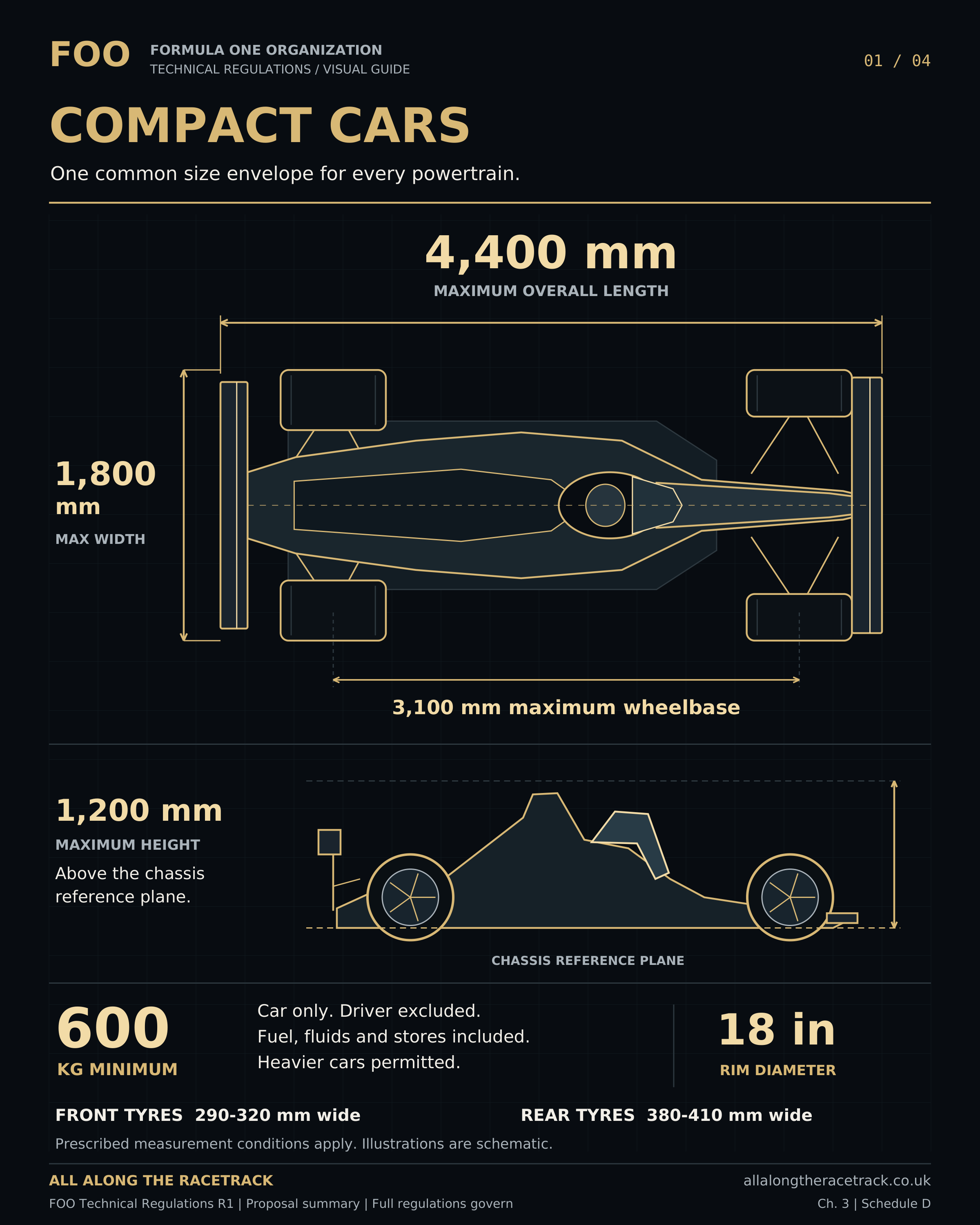
3.1.1 Every architecture shall comply with the common dimensional requirements in Schedule D. Maximum overall length is 4400 mm and maximum overall width is 1800 mm under its prescribed measurement conditions. Compliance shall cover the declared operating range, including aerodynamic loading, elastic deformation and commanded movement, subject only to the explicit wheel-movement and measurement provisions in that Schedule.
3.1.2 Maximum height is 1200 mm above the chassis reference plane and maximum wheelbase is 3100 mm. Schedule D specifies inspection conditions. Ordinary suspension-induced wheel movement is permitted within a declared safe movement envelope; deliberate wheelbase or track extension to circumvent inspection limits is prohibited.
3.1.3 Schedule D establishes the reference conditions for wheel position and the permitted envelope of normal steering and suspension movement. The allowance is limited to the components and movements expressly identified. It shall not permit aerodynamic bodywork to exceed its dimensional limits or allow deliberate extension of track or wheelbase to circumvent them.
3.1.4 Constructors shall declare all operating positions and relevant deformed shapes. Representative combined steering, suspension, tyre and aerodynamic movement shall preserve safe clearance from tyres, lines, cables, brakes and other critical parts.
3.1.5 Electronic movement limits relied upon for safety require validated failure behaviour. A software command in normal operation alone is insufficient containment evidence. A fault shall not intentionally release an assembly into a higher-performance configuration outside its permitted range.
3.2 Mass and driver provision
3.2.1 The minimum car-only mass shall be 600 kg throughout competition running, determined from the car in its actual condition under Schedule M, excluding the driver and personal equipment but including its remaining fuel, fluids and installed energy stores. The required post-race samples shall remain available, and the official mass shall be established before their removal, subject only to the controlled exceptional procedure in M3.1. No minimum component mass or architecture compensation is introduced unless expressly listed. There is no general maximum mass; higher actual mass requires appropriate safety evidence.
3.2.2 The minimum is not a target that constructors must achieve. A heavier powertrain or structure is permitted where the whole car complies. Energy-store mass remains part of the car; it is not deducted for battery-electric or hydrogen cars.
3.2.3 Structural, restraint, suspension, braking and other relevant operating assessments shall include the driver and personal equipment in addition to the car’s running mass excluding the driver. The assessment shall use the design allowance specified in Schedule D or the actual driver-and-equipment mass where greater, together with the relevant accommodation and load-distribution requirements. This allowance is not added to the car-only minimum for weighing purposes, and no ballast is required to equalise drivers.
3.2.4 Fixed, securely retained ballast is permitted where declared and inspected. It shall not move in operation or be replenished during the race. Fluid inventories shall not be disguised as ballast to circumvent their capacity or consumption requirements. This restriction does not prohibit the functional movement of components expressly permitted elsewhere, including approved suspension devices and mass dampers. Such mechanisms shall have a declared and verifiable function and shall not be used as a substitute for prohibited movable ballast or independently commanded mass redistribution.
3.2.5 Weighing shall follow Schedule M. The driver and personal equipment shall be removed; the installed seat and harness remain. No fluid, replacement tyre, added material or external supporting load may restore mass before the official weighing.
4 Powertrain architectures and performance
4.1 Eligible architectures
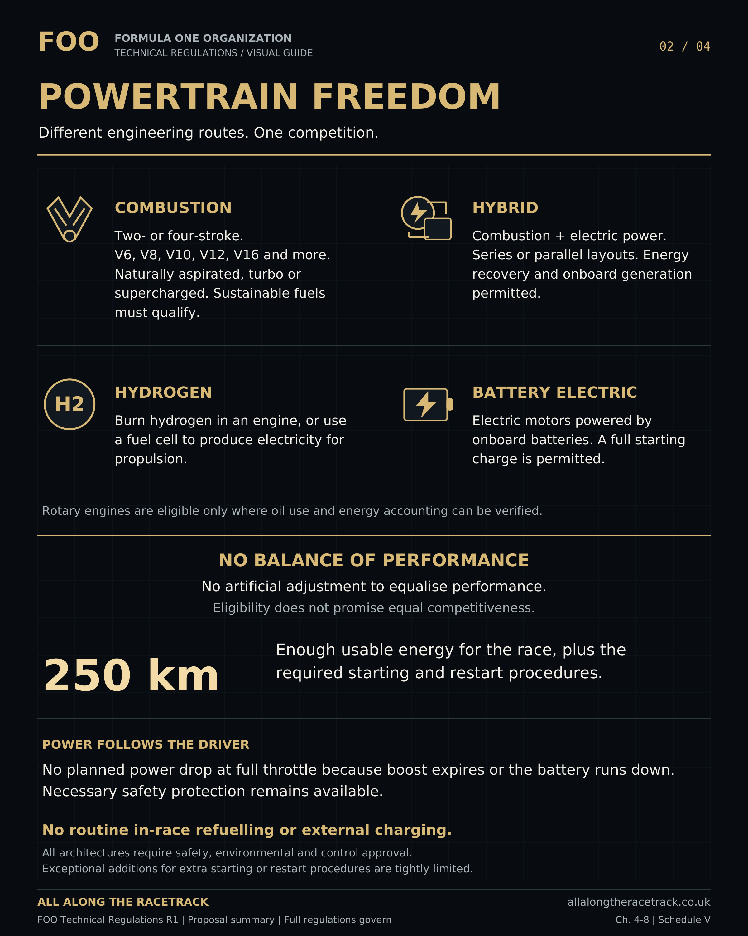
4.1.1 Four-stroke and two-stroke piston combustion engines are permitted. Cylinder number and arrangement, displacement, rotational speed and induction technology are unrestricted, subject to the applicable safety, fuel, environmental and control requirements. Permitted arrangements include, but are not limited to, V6, V8, V10, V12 and V16 engines. Naturally aspirated, turbocharged, mechanically supercharged and electrically assisted induction systems are permitted.
4.1.2 Rotary combustion engines are conditionally eligible where oil consumption, lubrication and energy accounting can be reliably verified. Necessary metered consumptive lubrication shall be distinguished from deliberate additional fuelling under Article 7.
4.1.3 Battery-electric propulsion, hydrogen combustion, hydrogen fuel cells, series hybrids and parallel hybrids are eligible. A combined or switchable series-parallel configuration requires explicit approval of every mode and transition against all applicable restrictions. Approval of an architecture or mode transition does not authorise an automatic selectable propulsion-ratio change or clutch assistance otherwise prohibited by Article 8. Source coordination that does not perform such a change remains permitted under Article 4.3.
4.1.4 Shaft-power gas turbines and free-piston electrical generators are not initially authorised architectures. A constructor may propose them; competition use requires an appropriate published regulatory amendment as well as safety approval.
4.1.5 Rear-wheel drive and all-wheel drive are permitted. Front-wheel-drive-only propulsion is prohibited. There is no prescribed number of electric machines, but every machine and energy path shall be declared. Complexity shall not obstruct reliable verification. A fault shall not convert an all-wheel-drive installation into a front-only propulsion mode for continued competition. Its approved safety strategy shall inhibit that mode and provide a controlled safe stop without removing driver-commanded steering or braking.
4.1.6 Atmospheric air shall be the combustion oxidiser. Stored supplemental oxidiser and oxygen enrichment are prohibited; approved oxygen-bearing fuel constituents are assessed as part of the fuel specification. Non-wheel reaction propulsion is prohibited.
4.2 Energy conversion
4.2.1 Brake-energy recovery, engine-driven generation and exhaust-energy recovery are permitted. Electrical energy may support wheel propulsion or turbo operation. Engine-driven generation is expressly permitted for both series and parallel arrangements subject to the other restrictions.
4.2.2 No lap-by-lap charge-neutral requirement applies. Starting stored energy may be consumed across the race, provided the approved response and required race duty remain achievable. A full starting battery is permitted, not mandatory.
4.2.3 All energy stores, generators, recovery devices and auxiliary energy paths capable of contributing to propulsion shall be declared. Propulsion energy stores not expressly permitted by these Regulations, including flywheel and hydraulic accumulators used for propulsion, require a published regulatory amendment and the applicable safety approval before competition use. This restriction does not prohibit otherwise permitted accumulators or energy stores serving exclusively auxiliary functions.
4.3 Sustained propulsion
4.3.1 Propulsion demand shall originate from accelerator input through the approved relationship for the selected setting. Electronics may coordinate power sources using permitted physical conditions, efficiency and component limits to fulfil that demand. Source coordination remains subject to the traction-control prohibition in Article 10.1.5.
4.3.2 Autonomous tactical scheduling of assistance or withdrawal is prohibited. This includes scheduling by circuit position, predicted lap performance, competitor information, elapsed boost time or a planned depletion strategy, whether directly measured or reconstructed. Battery state of charge, temperature and other approved component states may inform internal source coordination to fulfil the approved combined propulsion response and remain within validated limits. This shall not authorise a state-dependent reduction of that response, tactical assistance scheduling, a timed boost window or prescribed driver setting changes. Consumption of the declared starting energy under a validated driver-demand relationship is not, by itself, prohibited tactical scheduling.
4.3.3 During sustained full-accelerator demand, the combined powertrain shall deliver the approved propulsion response for the selected setting and applicable operating conditions throughout the required race duty. The reference response shall not be reduced because of battery depletion, elapsed assistance time or predictable thermal inadequacy. Normal speed-dependent characteristics, validated gearshift transients and expressly permitted interventions shall be assessed separately. Changes in vehicle speed alone shall not establish compliance or non-compliance.
4.3.4 Individual power-source contributions may change while combined propulsion is maintained. Electrical or engine-generated energy may not be redirected in a way that creates an undeclared reduction in driver-requested propulsion.
4.3.5 Drivers may deliberately select approved lower or higher power settings. Each has a repeatable response and shall satisfy the sustained-duty requirement. A setting shall not automatically expire, return to another setting or initiate a programmed sequence. Selection shall not command propulsion independently of accelerator demand.
4.3.6 Compliance shall not depend on prescribed setting changes or compulsory lift-and-coast to prevent depletion. Voluntary energy saving by the driver is permitted. The declared maximum response shall represent sustainable operation under the required duty, not an unsustainable short peak.
4.3.7 Protective intervention shall remain available whenever safety requires it. Recurrent protective derating in ordinary conditions shall be investigated as a potential design or compliance deficiency. A genuine isolated failure does not by itself establish a systematic breach.
4.3.8 Restoration after a fault shall preserve driver authority and avoid an abrupt uncommanded increase. Relevant faults, cause measurements and output changes shall be recorded. Remote team reset or restoration is prohibited.
4.3.9 Schedule V governs verification. Its investigation thresholds are not permissions to clip. Technology competitiveness and lap-time equality are not acceptance criteria.
5 Fuels and fuel quality
5.1 Eligibility and formulation
5.1.1 All fuels used for propulsion or onboard energy generation, including hydrogen supplied to combustion engines or fuel cells, shall meet Schedule E lifecycle eligibility and the applicable safety and quality requirements. Zero tailpipe carbon dioxide alone does not establish eligibility. Sustainable fuel is not synonymous with zero exhaust emissions.
5.1.2 The complete delivered formulation, including additives and blend constituents, shall be declared and traceable. Food or feed crops as primary fuel feedstock are excluded; eligible waste, residue and other non-food pathways require documented origin and assessment.
5.1.3 Formulation freedom remains subject to combustion compatibility, material compatibility, handling hazards, emissions assessment and reliable identification. Additives shall not create an undeclared energy, oxidiser or hazardous-substance route.
5.1.4 Suppliers shall provide reference samples or an approved alternative identification method for each specification and batch. FOO may compare delivered and onboard fuel. Changes to approved formulation require review before use.
5.2 Supply treatment and measurement
5.2.1 Fuel shall remain within its approved specification and operating conditions during storage and use. Approved preparation processes, including pressure regulation, temperature conditioning, vaporisation and mixing with combustion air, are permitted within their assessed limits. Any process that chemically converts the fuel or selectively changes its constituent proportions requires explicit approval of the resulting compositions, energy paths, safety implications and measurement method before use.
5.2.2 Fuel quantity, energy content and all injection paths shall be measurable under an approved method. No common fuel-flow or total-energy performance cap is introduced by these Regulations. Measurement serves declared capacity, sustainability, safety and anti-circumvention requirements.
5.2.3 Water injection is permitted using declared purity and composition. Undeclared additives are prohibited. A combustible injection mixture shall be treated as fuel for relevant energy, eligibility and capacity purposes, not as unaccounted cooling water.
5.2.4 Sample requirements are in Schedule M. Hydrogen shall use an approved sealed sampling or equivalent identification arrangement appropriate to its physical state; liquid-fuel sample volume shall not be applied mechanically to hydrogen.
6 Energy storage race capacity and replenishment
6.1 Capacity assessment
6.1.1 The car shall carry sufficient usable fuel and stored energy for its intended 250 km race duty at the circuits for which it is entered, accounting for the sporting rule on completion of a whole lap, normal starting procedure, return running, samples and justified operational margins. Permitted onboard generation and energy recovery may be included in the validated energy balance, without double counting or reliance on compulsory energy-saving measures contrary to Article 4.
6.1.2 The assessment shall additionally cover a cumulative allowance equivalent to three extra formation or restart laps at the relevant circuit, using the approved procedural duty profile, together with the associated stationary auxiliary duty specified in Schedule V. Actual additional procedural running shall count cumulatively against this allowance, which shall not reset after suspension. Schedule V includes 15 minutes of cumulative additional stationary auxiliary duty beyond the normal published starting timetable. Extra stationary time is accounted for separately from additional laps; neither allowance automatically resets or enlarges the other.
6.1.3 Capacity shall be based on validated consumption and energy balance for the actual car, including loads, auxiliaries, environmental conditions and usable residual limits. No arbitrary universal reserve percentage applies. Contingencies, samples, retained working inventory and headspace shall be separately identified without double counting.
6.1.4 The common scenario method in Schedule V, applied to circuit and event data, shall establish coverage without separate safety certification for every circuit. Before participation, the constructor shall demonstrate that the entered configuration can fulfil the required duty within its validated capacity envelope and comply with Article 4. A configuration that depends on compulsory energy saving, forced setting changes or predictable clipping to complete that duty shall not be accepted.
6.1.5 Traction-battery capacity shall use demonstrated usable energy at the declared temperature, ageing and power conditions, not nominal cell capacity alone. Hydrogen capacity shall account for its approved storage state, delivery limits and inaccessible residual contents.
6.2 Storage and transfer safety
6.2.1 Fuel vessels, hydrogen storage and traction batteries shall be located, retained and protected under Article 16 and Schedule S. Fluid or electrical connections shall remain compatible with credible crash deformation and emergency isolation requirements.
6.2.2 Fill, charge, vent and service connections shall be identifiable, protected from accidental operation and designed for the relevant pressure, temperature and electrical conditions. Incorrect connection and uncontrolled release shall be prevented or safely detected.
6.2.3 Tanks and stores shall not be used as unapproved movable ballast. Deliberate fluid transfer for an independent vehicle-balance function is prohibited; necessary transfer to provide fuel or operate an approved system shall be declared.
6.3 Race replenishment prohibition
6.3.1 Routine refuelling, external traction charging, fluid replenishment and replacement of fuel vessels or traction stores are prohibited during the race-restriction period defined in Article 2. A red flag does not reopen normal servicing permissions.
6.3.2 Where unforeseen or safety-related starting or restart procedures exceed, or are expected to exceed, the cumulative three-extra-lap allowance or the 15-minute additional stationary allowance in Schedule V, the Race Director may authorise supervised additional fuel or equivalent electrical energy. The authorisation shall state the extra procedural running or stationary duration, eligible quantity, timing, method and oversight. The permitted quantity shall cover only the net additional procedural consumption beyond the relevant allowance, determined from the validated consumption of the actual car and reconciled against racing or procedural duty already counted or displaced. The same use shall not be counted as both an extra lap and stationary duty. Equal treatment means covering the same additional authorised duty, not identical fuel or electrical quantities. Replenishment shall occur only while the car is stationary, at an authorised location and under an approved safe procedure.
6.3.3 Exceptional additions shall cover only the extra authorised procedural duty. They shall not restore ordinary racing energy, correct an inadequate initial load or replenish more than the approved store can safely contain. Cumulative additions and procedural use shall be reconciled without resetting the allowance.
6.3.4 Exceptional replenishment does not permit oil, injection-water or coolant additions, store replacement or unrelated work. Necessary safe thermal conditioning for an authorised electrical charge may be included expressly in the instruction; it shall not become general external performance cooling.
6.3.5 Existing fluid removed during an otherwise permitted repair may be returned only under supervised identification and quantity control. No new fluid may be substituted under this provision. The Sporting Regulations determine whether the repair itself is allowed.
6.3.6 Only a formal sporting decision establishing a new race may reset the restriction period. A team shall not treat a suspension, aborted start or restart as a new event for replenishment purposes.
7 Lubricants cooling and other fluids
7.1 Lubrication inventory
7.1.1 The oil tank and complete lubrication system shall be sized to validated engine and system requirements only: working inventory, cooling and de-aeration needs, normal consumption, sampling, necessary margins and expansion headspace. Hidden auxiliary reservoirs and excess inventory intended for combustion are prohibited.
7.1.2 Constructors shall substantiate requirements from their design, testing and intended race duty. A self-declared requirement is not sufficient evidence. Inventory shall include tank, galleries, sumps, lines, accumulators and other relevant volumes. The assessment shall cover the race duty and procedural allowance defined in Article 6, together with the declared operating conditions and component service limits. Any margin shall be supported by evidence and shall not constitute an unrestricted additional allowance.
7.1.3 Deliberate lubricant use as additional fuel is prohibited. Normal incidental consumption shall be measured and bounded through an approved consumption model. Tank sizing supplements, but does not replace, consumption monitoring and inspection.
7.1.4 Rotary or other inherently consumptive lubrication may be approved only where the necessary quantity, injection paths and control law are auditable. Metered lubricant entering combustion shall be included in the relevant energy and environmental inventory. Any energy contribution from necessary lubricant consumption shall be accounted for. Lubricant quantity, formulation and delivery shall not be selected or controlled to provide additional fuelling beyond the validated lubrication requirement.
7.1.5 Oil replenishment during the race is prohibited, including during exceptional procedural refuelling. Sample quantities shall be included without counting the same retained fluid both as minimum operating inventory and as freely removable sample.
7.2 Fluid chemistry and environmental assessment
7.2.1 Lubricants, hydraulic fluids, coolants, brake fluids and service chemicals shall be suitable for their function and assessed for hazards, containment and end-of-life treatment. The lowest practicable impact compatible with safety, reliability and verification shall be pursued.
7.2.2 Bio-based content, biodegradability, toxicity, bioaccumulation and lifecycle greenhouse emissions are distinct properties. No single label establishes that the finished formulation, including additives, is preferable or suitable. Claims shall identify the assessed property and method.
7.2.3 Recoverable fluids shall follow the approved collection route. Intentional discharge during normal operation is prohibited except where expressly permitted elsewhere in these Regulations for an approved process. Necessary safety pressure relief remains permitted, shall be safely directed and shall not be used as a routine means of fluid disposal or performance control.
7.3 Cooling and thermal systems
7.3.1 Cooling layout, fluid choice and thermal storage are free within safety and other technical restrictions. Thermal stores and their contents count toward car mass. Their energy paths and recharge or servicing requirements shall be declared.
7.3.2 Sealed cooling installations shall maintain integrity under validated conditions. Cooling-medium discharge shall not be used to generate propulsion, aerodynamic assistance or artificial mass reduction. Normal fuel-cell product water is treated separately from deliberate coolant disposal.
7.3.3 External cooling intended to restore or improve competitive performance after the initial race-start signal is prohibited, except for expressly authorised safe conditioning associated with exceptional charging under Article 6. Emergency cooling necessary to protect people or contain an immediate hazard is permitted under official supervision. Such intervention does not itself authorise the car to resume competition; any return shall require safety clearance and compliance with the Sporting Regulations. Ordinary pre-race preparation remains subject to those Regulations.
7.3.4 Cooling capability shall support the approved powertrain response and validated operating envelope. Repeated ordinary thermal derating does not establish compliance merely because the protective function works correctly.
8 Gearboxes clutches and torque distribution
8.1 Transmission freedom
8.1.1 Gearbox layout, discrete gear count, ratios, materials and manufacturing methods are free subject to safety, inspection and driver-control requirements. Continuously variable transmissions are prohibited. Fixed-ratio electrical drives are permitted. The continuously variable transmission prohibition applies to mechanical power-transmission arrangements providing a continuously variable effective ratio to the driven wheels. Electrical energy conversion in an approved series-hybrid architecture is not, by itself, a continuously variable transmission. Combined architectures remain subject to approval of their complete mechanical and electrical power paths.
8.1.2 Each normal change of a selectable propulsion gear ratio shall require a separate driver command. Automatic shift sequences, repeated shifts from a held command and storage of a rejected command for later automatic execution are prohibited. Approved actuation, torque coordination and speed matching necessary to execute an accepted request are permitted. An unsafe request may be rejected, but shall not cause another propulsion gear to be selected autonomously. A new driver command shall be required following rejection.
8.1.3 The driver shall be able to select reverse from a suitable stationary safe condition. Reverse may be mechanical or electrical. An external neutral or equivalent recovery function shall permit safe handling without enabling propulsion.
8.2 Clutch control
8.2.1 Clutch demand shall be controlled by the driver except for approved gear-change execution, anti-stall, authorised standing-start launch control and a necessary emergency safety disengagement. No other clutch assistance is permitted. This paragraph governs clutches that connect, disconnect or regulate a propulsion transmission path. An auxiliary-device clutch shall not be used to circumvent it.
8.2.2 Anti-stall shall prevent a genuine imminent stall and shall not optimise launch or traction. Emergency disengagement shall address a hazardous condition and be recorded; it shall not become a routine performance-control function.
8.3 Differentials and all-wheel drive
8.3.1 Passive mechanical differentials and limited-slip mechanisms are permitted. Their natural torque or speed-dependent behaviour is not itself prohibited electronic traction control.
8.3.2 Electronically controlled differential locking and automatic front-to-rear torque distribution are conditionally permitted only after approval of their input signals, control laws and operating boundaries. Except within expressly permitted standing-start launch functions, they shall not use measured or inferred tyre slip, available grip or yaw error to regulate traction or correct vehicle rotation. An incidental effect on tyre slip does not establish permission for a slip-regulating function. Compliance shall be assessed from the complete control behaviour, including interactions with other systems. The general propulsion traction-control prohibition in Article 10.1.5 also applies.
8.3.3 Independent left-to-right propulsion torque vectoring is prohibited. Natural torque differences through an approved mechanical differential are permitted. Independent motors shall not provide a prohibited function through separate commands. Authorisation of standing-start launch control does not permit independent left-to-right propulsion torque vectoring. Approved anti-lock braking and necessary fault protection remain governed by their specific provisions and shall not create a general torque-vectoring permission.
8.3.4 Component overspeed or overload protection shall have justified component-based thresholds. Calibrating it to provide routine tyre-slip control is prohibited. Shared ABS, steering or suspension information remains subject to the same drivetrain restrictions.
8.3.5 If a conditional control function cannot be reliably distinguished from prohibited assistance, it shall be simplified or excluded before use. Any category-wide change shall be published through the regulatory process; approval cannot silently override the prohibition.
8.3.6 Gear, shaft, clutch and rotating-machine failure containment shall address the credible stored energy and loads of the installed system. Supplier certification alone shall not establish installation safety.
9 Electrical systems and communications
9.1 Architecture and isolation
9.1.1 Electrical layout, controller count and propulsion-machine arrangement are free where the complete system is safe and auditable. All energy stores, voltage domains, isolation devices and potential back-feed paths shall be declared.
9.1.2 Hazardous electrical systems shall have appropriate insulation, contact protection, interlocks, fault detection and controlled discharge. Stored energy shall remain identified after isolation. Safety-critical auxiliary functions shall be retained where their loss would create a greater immediate hazard.
9.1.3 Traction stores shall be assessed for electrical, thermal, mechanical and environmental failure, including cell faults and propagation consequences. Monitoring shall identify unsafe operating conditions and initiate the approved protective response. Continued racing is not permitted merely because an alarm has been acknowledged.
9.1.4 Wiring and connectors shall be protected against movement, abrasion, heat and incorrect assembly. Charging and maintenance interfaces shall prevent unsafe energisation and shall follow the declared isolation sequence.
9.2 Communication boundary
9.2.1 Remote control of regulated vehicle functions by any external person, system or service is prohibited, except for the specifically authorised official safety-status interface under Article 9.2.4. External commands shall not alter propulsion, steering, braking, aerodynamics, suspension, protection thresholds or control configuration. Remote fault clearing, controller resets and commands stored for later execution are also prohibited. Permitted stationary servicing under Article 9.2.5 and physical operation of the prescribed external emergency shutdown controls remain separately governed.
9.2.2 Outbound telemetry and incoming messages strictly necessary to maintain the communication link are permitted, provided those messages cannot change regulated control behaviour, clear faults, reset controllers, alter required recording or load instructions for later execution. Voice radio may carry human advice but shall not provide machine-readable control instructions to onboard systems.
9.2.3 Timing, positioning and competitor information may be used for permitted displays and official functions. Approved separation shall prevent those paths from supplying prohibited control inputs. Separate physical computers are not mandatory if equivalent separation is demonstrated.
9.2.4 Only specifically authorised, authenticated official safety-status inputs may enter the vehicle control system, for example to identify an applicable neutralisation state under the Sporting Regulations. This is not general remote actuation permission. The permitted signal, receiving function and driver interaction shall be published before use. An official safety-status message shall identify only the authorised state and any expressly specified associated parameter. It shall not provide arbitrary actuator commands, software changes or team-specific performance instructions. The approved onboard response, any required driver action and the response to invalid, stale or lost messages shall be specified and recorded. The permitted limiter response and loss-of-status behaviour are defined in T5.6. A pit-lane or neutralisation limiter may cap positive propulsion, but shall not initiate friction braking, a gear change or steering assistance. Driver braking and permitted accelerator-release retardation remain under Article 13. Valid limiter intervention shall be separately recorded and excluded from ordinary clipping assessment.
9.2.5 Software, calibration or model loading requires a stationary car in the designated service condition, propulsion disabled and an approved physical connection. Wireless updates are prohibited. Race-restriction servicing permissions still apply; this clause does not authorise work during a suspension.
9.3 Configuration and records
9.3.1 Every regulated controller and software version shall be identifiable. Configuration checks shall include boot software, executable logic, calibration, relevant retained state and connected devices capable of influencing control.
9.3.2 Logging and calibration functions shall be protected against unauthorised alteration. Required records shall identify omissions, resets, lost synchronisation and protection events. Loss of telemetry shall not erase the onboard record.
9.3.3 Missing or defective records do not, by themselves, establish that a prohibited performance function was used. Failure to meet a mandatory recording requirement remains a separate compliance matter. The constructor shall provide adequate alternative evidence where available. Where compliance of a regulated function cannot be established, that function shall not continue in use until adequate verification is restored; persistent deficiencies may result in withdrawal of its approval.
10 Electronic control and driver interfaces
10.1 Permitted responses
10.1.1 Each automatic function shall have declared objectives, inputs, calculated states, outputs and limits. Restrictions apply equally to direct signals, reconstructed information and data passed through other controllers.
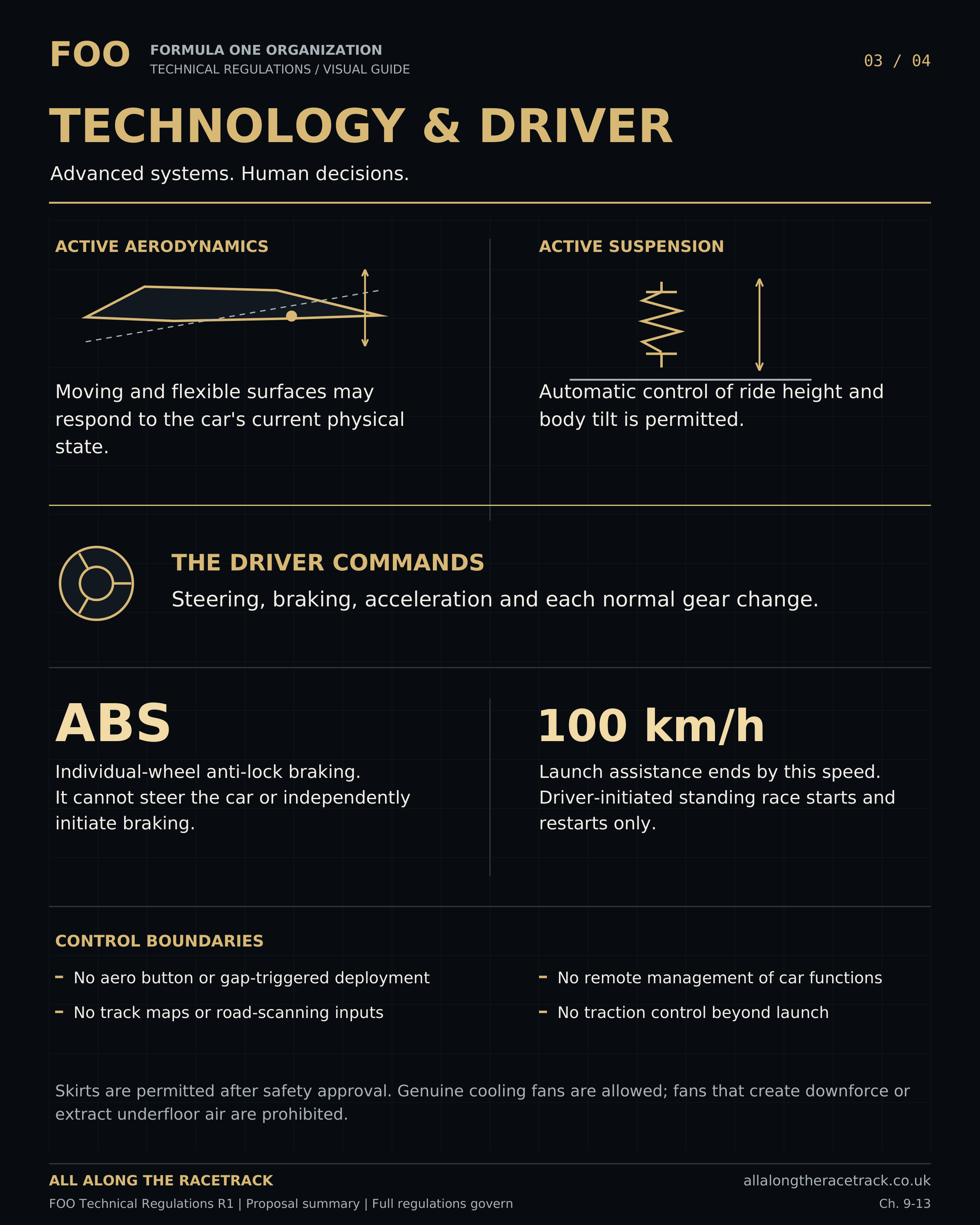
10.1.2 Aero and suspension may respond to present physical state, including approved speed, airflow, ride height, attitude, acceleration and load measurements. They shall not use forward-looking sensing, circuit maps, lap sequences, competitor gaps or reconstructed track location. Forward-looking sensing means measuring road geometry, surface condition or other features ahead of the car to prepare a control response before those features reach it. Sensor orientation alone does not determine eligibility. Measurement of local airflow or the car’s present physical state remains permitted within the approved input boundaries.
10.1.3 Prediction of the immediate physical response from current state and driver inputs is permitted. Prediction of an upcoming corner or surface feature from circuit knowledge is prohibited. Local wake response is permitted; identification of a competitor or gap to trigger overtaking assistance is not. Recent measurement history may be used for approved filtering, state estimation and prediction of immediate vehicle response. It shall not be used to recognise a circuit segment, reconstruct a lap sequence or anticipate a location-specific manoeuvre. The retained history and calculated states shall be declared and auditable.
10.1.4 Integrated aero and suspension control is permitted. A prohibited aerodynamic command remains prohibited when implemented through suspension movement. Driver suspension settings may change suspension characteristics but shall not act as direct low-drag or other aerodynamic deployment controls. Steering, braking and accelerator inputs may inform an approved prediction of physical vehicle response. They shall not operate as coded triggers for aerodynamic modes or deployment sequences unrelated to that response. Driver-selected suspension settings shall have a demonstrable suspension function; any associated aerodynamic effect shall remain subject to the approved integrated control law.
10.1.5 Except for the expressly authorised standing-start launch function under Article 10.3, no system shall regulate positive propulsion torque, including its production, transmission or distribution, for the purpose of preventing or reducing driven-wheel spin or maintaining a target driven-wheel slip. This restriction applies to measured or inferred slip and grip, irrespective of the mechanism, controller location or distribution of the function. Normal powertrain characteristics, driver-requested propulsion changes, approved passive mechanical differentials, permitted gear-change execution, genuine anti-stall and justified component protection remain permitted within their specific restrictions. Anti-lock action on braking or regenerative retardation remains governed by Article 13 and shall not authorise positive-propulsion traction control.
10.1.6 Active aerodynamic and suspension functions may regulate their approved physical quantities, including platform attitude, ride height, loading and aerodynamic balance. They shall not select a target vehicle path or regulate a yaw error or driven-wheel-slip error to correct the driver’s driving inputs. An incidental improvement in grip, balance or stability from an otherwise permitted physical-state response is not prohibited. Passive geometric and compliance effects remain governed by their specific provisions.
10.2 Adaptation and software development
10.2.1 Bounded, declared adaptation for physical changes such as sensor offset, wear or temperature is permitted where it maintains the approved function. Relevant adaptive parameters and retained information shall be inspectable.
10.2.2 Systems shall not learn circuit-specific strategies or develop prohibited driving assistance. Executable logic and approved control models shall not rewrite or replace themselves during running. Approved bounded parameter adaptation is distinct from changing the control function.
10.2.3 Simulation, optimisation and machine learning may be used in development. The deployed system shall nevertheless have verifiable behaviour and validated limits. Invalid estimates shall lead to the approved safe response, not self-extension of limits.
10.3 Launch control
10.3.1 Launch assistance is permitted only for an authorised standing race start or standing restart, armed and initiated by the driver. Automatic detection of the start signal to initiate departure is prohibited. Formation, pit-exit and rolling starts do not qualify.
10.3.2 The approved launch function may regulate the expressly authorised clutch and propulsion functions, including launch-specific slip regulation. It shall not provide automatic steering, selective braking, yaw correction or automatic gear shifts. Launch assistance shall not provide independent left-to-right propulsion torque vectoring.
10.3.3 Launch assistance shall terminate at 100 km/h validated vehicle speed, or earlier upon driver cancellation, full accelerator release, a new braking demand after departure, a stall ending the attempt, return to rest or invalid required measurements. Initial brake holding before departure shall not by itself count as cancellation.
10.3.4 No five-second termination limit applies. Once a termination condition has occurred, falling below 100 km/h, changing gear, reapplying the accelerator or resetting a controller shall not reactivate launch assistance. Rearming requires a new authorised standing start or standing restart and a fresh driver arming action. A partial accelerator reduction that does not meet a termination condition shall not reset or extend the launch function.
10.3.5 Termination shall remove launch-specific assistance within the Schedule V transition limit and retain the normal approved propulsion response. It shall not act as expiry of electrical boost. The state machine shall include disarmed, armed, active, terminating and locked-out states.
10.4 Driver information and controls
10.4.1 Displays may show operating information, energy, consumption, estimated range, lap and sector times, timing deltas and powertrain-based shift indications. Selection of propulsion gear ratios remains subject to Article 8. Protective rejection of an unsafe shift, torque reduction or emergency disengagement shall not authorise autonomous selection of another propulsion gear.
10.4.2 Automated instructions prescribing braking points, lines, steering or circuit-specific deployment sequences are prohibited. Energy information shall not become a programmed series of lift or setting-change prompts. Ordinary human radio advice remains permitted under the Sporting Regulations.
10.4.3 Safety warnings may be visual, audible or non-directional tactile signals. Steering or pedal feedback shall not provide corrective driving guidance. Warnings do not independently authorise steering, braking or propulsion intervention.
10.4.4 Every performance-related cockpit control shall have a declared function. A single action shall not initiate a prohibited sequence or timed intervention. Physical driver selection of an approved power setting remains governed by Article 4.
11 Aerodynamics and ground contact
11.1 Development freedom
11.1.1 Aerodynamic shape, layout, asymmetry, flexibility and powered movement are permitted within the common envelope, safety requirements and control restrictions. No prescribed wing profile, floor concept or general stiffness limit is introduced. Compliance with the dimensional limits shall cover the declared operating range, including aerodynamic loading, elastic deformation and commanded movement, subject only to the explicit measurement conditions and exceptions in Schedule D.
11.1.2 Active aerodynamic surfaces and suspension may coordinate to manage ride height, aerodynamic balance and response to permitted physical conditions under Article 10. Automatic changes that reduce drag are permitted within those requirements. Driver-commanded aerodynamic deployment and deployment triggered by competitor gaps, designated circuit zones or reconstructed track position are prohibited.
11.1.3 Components shall be validated over their declared loaded shapes and movement range. Tests shall address static strength, combined loads, fatigue, oscillation, flutter, attachments and actuator loads. Safe behaviour is required under credible faults, including interacting aero and suspension failures.
11.1.4 Failure assessment shall consider debris, changes in aerodynamic balance and controllability, including the transition into the proposed safe condition. Unchanged performance after a failure is not required. No universal fail-flat position is prescribed; the constructor shall demonstrate that its proposed response meets the applicable safety acceptance criteria, subject to FIA approval.
11.2 Skirts and wear surfaces
11.2.1 Fixed, flexible, sliding and actively positioned skirts are permitted following safety approval. Active mechanisms remain subject to Article 10. Contact surfaces, movement, materials and intended contact conditions shall be declared.
11.2.2 Skirts and other designated wear surfaces shall be retained and validated for wear, repeated contact, representative impacts and snagging. Exposed mechanisms shall not present an unacceptable destabilising or debris hazard.
11.2.3 Evidence shall address progressive wear, loss of sealing, jamming, detachment and asymmetric failures. Declared service limits shall preserve structural integrity and acceptable controllability through the required duty. Retention of initial aerodynamic performance is not required, but foreseeable wear shall not produce an unassessed unsafe change in aerodynamic behaviour.
11.2.4 Contact forces and materials shall not create unacceptable track-surface damage or hazards to following cars. Common acceptance criteria shall apply; separate constructor approval at each circuit is not required.
11.2.5 Replaceable skirts do not create a routine race replacement permission. Servicing follows the Sporting Regulations. Other structures shall not rely on uncontrolled ground contact outside their validated intended use.
11.3 Cooling fans and exhaust
11.3.1 Passive intake, heat-exchanger, duct and outlet shaping is free within the general limits. Active cooling shutters affecting aerodynamics shall also comply with the active-aero provisions.
11.3.2 Powered fans may serve genuine cooling duties with declared heat-rejection requirements and control logic. Fans, blowers, compressors, stored-pressure discharge and equivalent powered-flow arrangements shall not be configured or operated to generate aerodynamic downforce, provide powered underfloor extraction, seal the floor aerodynamically or propel the car by reaction thrust. The prohibition applies irrespective of the source of power. Incidental effects of an otherwise compliant cooling installation shall be assessed under Article 11.3.3.
11.3.3 A dual-purpose cooling installation shall not perform a prohibited powered aerodynamic function. Unavoidable incidental effects shall be assessed in context; a non-zero measured force alone is not an automatic breach. Fan operation shall not be scheduled for manoeuvre-specific aerodynamic benefit.
11.3.4 Exhaust shall not be deliberately directed into floor tunnels, diffusers, skirt-sealing regions or onto aerodynamic surfaces to improve their effectiveness. Engine operation shall not produce exhaust primarily for aerodynamic benefit. Necessary generation and protection remain permitted.
11.3.5 Constructors shall declare flow paths, outlet geometry and control functions and demonstrate compliance with Schedule V before introducing the installation. Compliance with an outlet box alone shall not establish compliance with the functional prohibition.
12 Suspension and steering
12.1 Suspension
12.1.1 Passive and active suspension, coupled axles, self-levelling, inerters, mass dampers and other declared mechanisms are permitted subject to safety and control restrictions. Springs of a particular type are not mandatory.
12.1.2 Powered adjustment whose function is to control toe or camber, whether individually or collectively, is prohibited. Geometry changes arising from the declared kinematics and compliance of an approved suspension are permitted. Suspension movement shall not be commanded to achieve a prohibited steering, toe, camber or yaw-control function. Eligibility shall be assessed from the mechanism and its control behaviour, rather than the name assigned to it.
12.1.3 The complete system shall be assessed for travel, loads, structural retention, operating pressure where relevant, actuator faults and loss of energy supply. Safety-critical members, uprights, bearings and mountings shall have defined inspection and life requirements.
12.1.4 Wheel tethers and suspension intrusion protection shall meet the applicable FIA requirements selected in Schedule S. Attachment design shall address the consequences of suspension failure for the survival cell and driver.
12.2 Steering authority
12.2.1 The driver shall command front-wheel steering through one steering wheel and an approved fixed steering characteristic. That characteristic may be nonlinear with steering-wheel position. Declared geometric and compliance effects arising from permitted suspension movement and loading are allowed. Automatic variation of the steering characteristic with speed, grip, circuit position or vehicle instability is prohibited.
12.2.2 Normal left-to-right angle differences from steering geometry are permitted. Rear steering and independent commands that select wheel angles beyond the approved driver-input relationship are prohibited. Separate front-wheel actuators, where approved, shall reproduce the prescribed driver-commanded steering geometry and shall not independently select wheel angles for handling optimisation.
12.2.3 Power assistance may reduce steering effort without independently choosing direction or overriding the driver. Mechanical or electronically generated feedback may represent physical steering loads and provide approved damping and centring characteristics. Its inputs and response shall be declared and auditable. Feedback shall not encode a recommended steering correction, target line or autonomous stabilising action.
12.3 Mechanical and by-wire implementations
12.3.1 Mechanical steering is the baseline option. Steer-by-wire without a physical shaft may be approved where independent validation demonstrates continued driver steering authority after the specified failures. Following the specified failures, the system shall retain sufficient driver-commanded steering capability to maintain control and bring the car to a safe stop within the validated operating envelope. Continued competitive operation is not required. Any degraded operating mode shall be identified to the driver and governed by the approved safety procedure.
12.3.2 Validation shall cover sensors, processing, communications, actuators, power supplies, transitions and common-cause failures. Duplicated controllers alone do not demonstrate redundancy. Failure transfer shall not cause an unsafe change in angle, effort or response. The assessment shall include relevant failures in shared electrical supplies and vehicle networks, including emergency propulsion shutdown. Retention of steering capability shall not depend solely on the continued availability of the normal propulsion power supply. The failure matrix, transfer limits, reserve-energy duration and evidence requirements in S3 apply. Passing nominal steering tests without the specified failures shall not establish approval.
12.3.3 Normal operation, feedback, calibration and failure modes shall be approved before introduction. Routine post-race checks shall cover configuration identity, diagnostics and relevant input/output records, with physical inspection or further testing as indicated.
12.3.4 Recorded normal running does not replace failure testing. Steering-column impact requirements or an approved equivalent for an alternative architecture shall be included in the FIA safety assessment.
13 Braking systems
13.1 Driver demand and fallback
13.1.1 Friction braking shall be provided at all four wheels. The brake pedal establishes demand through an approved repeatable relationship. Friction-system architecture, materials and cooling are free subject to safety and the explicit control limits.
13.1.2 Following the specified single failures, sufficient driver-commanded braking capability shall remain independently of the failed element to maintain control and bring the car to a safe stop within the validated operating envelope. Validation shall address relevant shared power, control and communication failures, including emergency propulsion shutdown. Conventional separate circuits and powered or by-wire arrangements shall meet the applicable safety acceptance criteria. Continued competitive operation after a failure is not required. Residual braking performance, driver effort and controllability shall satisfy S3, with regeneration unavailable. Failure response shall preserve driver authority and shall not create autonomous braking or yaw control.
13.1.3 Driver-selected front-to-rear brake balance is permitted. Regeneration blending shall preserve the approved total braking response and selected balance within the declared operating limits. Automatic departures are permitted only for approved anti-lock action or necessary fault response. Regeneration blending shall not independently optimise cornering, estimate an optimum handling balance or provide yaw assistance.
13.2 ABS and regeneration
13.2.1 Individual-wheel modulation to prevent locking is permitted. Unequal forces arising from legitimate anti-lock action are allowed; deliberately selecting them to steer or stabilise yaw is prohibited. Anti-lock control may reduce and restore friction-brake demand and reduce regenerative or engine-braking torque as necessary to prevent locking. Intervention shall remain within the approved driver-requested braking or accelerator-release response and shall not create an independent braking demand. Restoring braking after an anti-lock reduction does not constitute autonomous initiation of braking.
13.2.2 Recovery through driven wheels may fulfil driver braking demand. Regeneration shall be coordinated with friction braking and ABS, including where electric-machine torque cannot be independently reduced at each wheel.
13.2.3 The friction-braking system shall fulfil the approved brake-pedal response when regeneration is unavailable under normal operating conditions, including the declared limits of battery charge, temperature and energy acceptance. Transitions between regenerative and friction braking shall not cause an unsafe or unexpected change in response. Exceptional failures shall be managed under the validated fallback requirements of Article 13.1.2. Friction braking shall not be applied automatically to replace unavailable accelerator-release regeneration.
13.2.4 Lift-off engine braking and regeneration are permitted under an approved repeatable accelerator-release relationship. A low-retardation coast setting is permitted. Circuit-position scheduling and independent friction-brake application on accelerator release are prohibited. The approved relationship shall identify the effect of normal regenerative-energy acceptance limits, including a full battery. Changes in available retardation shall be predictable, safely transitioned and indicated where material to the driver. This does not permit autonomous friction-brake substitution or tactical location-dependent variation.
13.2.5 Brake-based traction control, brake-based differential action under acceleration and autonomous initiation of braking for cornering are prohibited. Legitimate driver braking while accelerator demand exists is not itself prohibited; the commanded response remains auditable.
13.3 Cooling and evidence
13.3.1 Passive brake-cooling shape is free. Active cooling elements shall meet the aero-control rules where applicable. Any separate powered cooling fan shall meet Article 11 and shall not be a prohibited wheel-mounted device.
13.3.2 Ordinary thermal interaction between brakes, rims and tyres is permitted. Dedicated onboard tyre heating and independent brake application to generate tyre heat are prohibited.
13.3.3 Validation shall include mixed and changing grip, wheel unloading, regeneration limits, ABS entry and exit, thermal capability and credible failures. Continued operation without regeneration is permitted only within the validated remaining capability.
13.3.4 Required records shall cover pedal demand, wheel speeds, relevant pressures or commands, regenerative torque, intervention state and faults. The method shall distinguish driver demand, blending and anti-lock action from prohibited assistance.
14 Wheels tyres and supplier development
14.1 Dimensions and rim integrity
14.1.1 Wheels and tyres shall meet Schedule D. Rim and tyre interfaces shall be jointly validated for the approved combination; compliance with nominal diameter alone does not establish compatibility.
14.1.2 Rim materials and manufacturing methods, including additive manufacture, are free subject to complete-assembly validation for load, pressure, speed, thermal exposure, fatigue and relevant impacts.
14.1.3 Rim shape may improve aerodynamics and brake or tyre cooling. Separate covers, fans, impellers and auxiliary airflow devices are prohibited. Integrally manufacturing a dedicated impeller does not make it permissible rim shaping.
14.1.4 Wheel seating, fastening and retention shall meet the applicable FIA baseline and provide reliable correct-fit verification. Service limits, damage checks, pressure integrity and monitoring-sensor attachment shall be validated. Each rim shall have traceable identification and service history.
14.2 Specification and competition use
14.2.1 Competing tyre suppliers are permitted. Each shall declare its initial range before the season, with different specifications for relevant temperatures and circuit demands. The initial range is not one universal compound for the entire calendar.
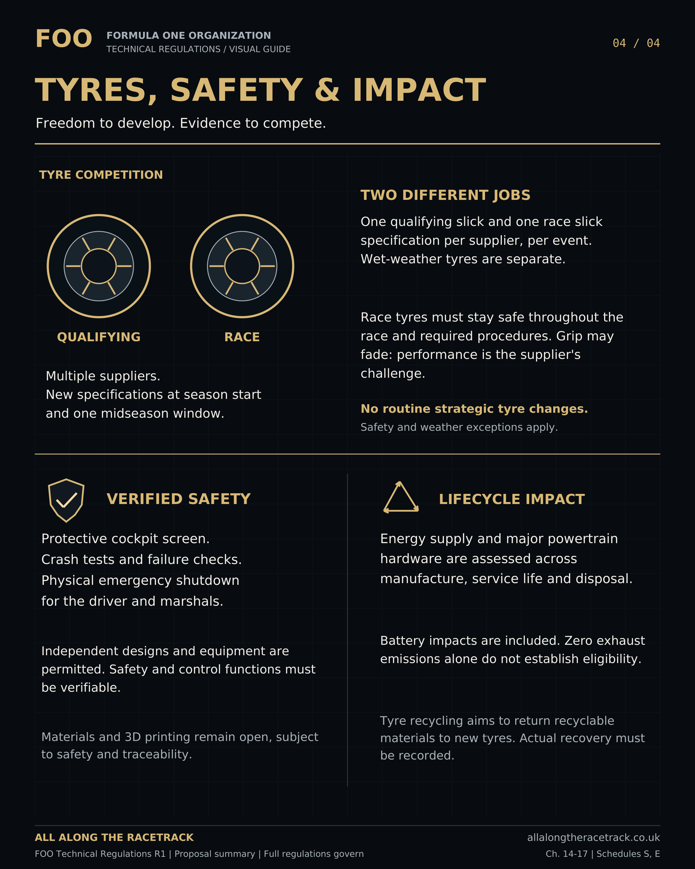
14.2.2 Each supplier shall nominate one qualifying slick and one race slick specification per event, with corresponding front and rear versions. Intermediate and wet specifications are separate categories. The nominated specifications shall be available on equivalent terms to all its customer teams.
14.2.3 Race slick tyres shall remain within their validated safe operating range and retain structural integrity throughout the race duty and procedural allowance defined in Article 6, when used within the approved conditions. Intermediate and wet tyres shall meet the corresponding duty within their declared weather and track-condition envelope. Qualifying tyres shall have a separately declared safe service allowance appropriate to qualifying use. Performance loss and grip degradation are competitive matters; no minimum retained grip is imposed.
14.2.4 Routine strategic tyre changes are prohibited. Damage, safety and weather replacement exceptions are governed by the Sporting Regulations. Poor pace alone does not create a technical safety exception.
14.2.5 Development and testing may continue throughout the year. New specifications may enter competition at the initial declaration and one published midseason introduction window. Outside-window safety changes require a documented issue, proportionate modification and approval. The midseason window permits approval and introduction of a revised declared range. Specifications within that range may subsequently be nominated for appropriate events under Article 14.2.2. Introduction of the revised range does not require every specification to be used at the first eligible event. Continued use of previously approved specifications shall be permitted unless their approval has been withdrawn or restricted.
14.2.6 Manufacturing variation within declared accepted tolerances is permitted. A deliberate material, compound or construction change is a specification change. Each tyre shall be uniquely identified to specification and batch; supplied, used, returned and retained tyres shall remain traceable.
14.3 Preparation and operating limits
14.3.1 Suppliers shall distinguish mandatory safety limits from performance advice. Limits shall define the relevant pressure, load, speed, temperature and alignment conditions, measurement method and any justified duration or cumulative-exposure allowance.
14.3.2 Teams may choose settings within validated limits. Compatibility shall account for the actual car’s mass, aero loads and configurations. A heavy car receives no larger tyre entitlement but must demonstrate compatibility.
14.3.3 External heating is permitted before initial use and before fitting an authorised replacement, within approved preparation limits. Onboard tyre heating, active pressure regulation, deliberate pressure bleeding and in-motion inflation are prohibited. Monitoring is permitted.
14.3.4 Inflation media shall have approved safety and environmental characteristics. Pressure-setting operations on stationary tyres are subject to the servicing rules; this permission does not open a race pressure-adjustment strategy.
14.3.5 Chemical treatment, machining or other deliberate alteration intended to change tyre compound, construction or performance characteristics is prohibited unless included in the approved specification and its declared preparation procedure. A preparation procedure shall not circumvent specification declarations, introduction windows or equivalent availability to customer teams. Mounting and cleaning products shall be approved for their intended use and shall not materially alter tyre characteristics. Normal wear during permitted use is not a modification.
14.4 Recovery and environmental responsibility
14.4.1 Suppliers shall aim to recover all recyclable constituent materials from end-of-life tyres and reintroduce them into new tyres for any application, without a prescribed timeframe. Recovered materials shall meet applicable quality and safety requirements.
14.4.2 Collection, traceability and truthful outcome reporting are mandatory. Reuse, material recycling, energy recovery and disposal shall be reported separately. Energy recovery is not material recycling.
14.4.3 Full return to tyre production is a development objective, not an immediate minimum recycled-content percentage. Limitations and alternative recovery routes shall be documented. Non-recyclable materials shall follow the applicable waste and hazardous-material provisions. Suppliers shall maintain a documented recovery and development plan identifying recyclable constituents, actual recovery routes, barriers to their use in new tyres and measures intended to address those barriers. Progress and outcomes shall be reported annually. A claim that a constituent is non-recyclable shall identify the technical or practical basis for that classification.
14.4.4 Safe rim reuse and recovery are encouraged within validated service limits. Environmental objectives shall not require unsafe tyre reuse, unvalidated retreading or structural repairs. Environmentally motivated specification changes remain subject to the normal introduction rules.
15 Materials manufacture and maintenance
15.1 Freedom and quality controls
15.1.1 Materials and manufacturing methods are free except for specific published restrictions and risks that cannot be adequately controlled. Conventional, composite and additive processes shall be assessed on their demonstrated suitability.
15.1.2 Safety-critical parts shall have proportionate material and process traceability. A successful prototype alone does not establish production consistency. Process controls shall address relevant defects and inspection capability. Safety-critical classification shall be based on the consequences of failure, including effects on other systems, rather than component size, cost or supplier designation. The constructor shall remain responsible for demonstrating compliance of the installed component, including where design, manufacture or inspection is performed by a supplier. Traceability shall connect the component or relevant batch to its material, manufacturing, inspection and acceptance records.
15.1.3 Additive manufacture shall address feedstock, build orientation and parameters, post-processing and defect detection. Composite manufacture shall address constituents, lay-up, bonding, cure and relevant hidden defects. Certification of a quality system is supporting evidence, not proof of component compliance. Acceptance criteria shall identify the relevant defect types, locations and allowable limits. Inspection methods shall have demonstrated capability appropriate to those criteria. Where relevant defects cannot be reliably detected, alternative manufacturing assurance, qualification testing and service limits shall provide the necessary safety evidence.
15.1.4 Material, supplier, process or location changes require assessment of their effect on approval. Further testing is required where prior evidence no longer applies. Non-conforming parts shall be withheld until compliance is demonstrated; an engineering concession cannot waive a mandatory rule.
15.2 Connections and installation
15.2.1 Bonded, welded, bolted and other joints shall be validated as complete connections under relevant combined loads, vibration, fatigue, thermal movement and environment. The connected materials and assembly process form part of the evidence.
15.2.2 Safety-critical fasteners shall resist unintended release through a validated arrangement. Procedures shall identify preparation, tightening, inspection and single-use requirements. Dissimilar-material joints shall address relevant corrosion, thermal movement and isolation.
15.2.3 Where a critical joint cannot be directly inspected, a justified alternative assurance method and service limit are required. Additional retention or redundancy shall follow applicable FIA requirements and assessed consequences, not a universal rule for every small attachment.
15.2.4 Pipes, hoses, cables and connections shall meet relevant transient pressure, temperature, electrical, vibration and chemical conditions. Routing shall prevent chafing, crushing, kinking, excessive tension and interference throughout permitted movement.
15.2.5 Hazardous interactions between leaks, electrical faults and hot surfaces shall be controlled by separation, shielding or equivalent validated measures. Incorrect hazardous connections shall be prevented or reliably detected. Installation checks shall follow assembly and relevant maintenance.
15.2.6 Disconnection procedures shall address retained pressure, fluid and electrical energy. A switch-off indication alone shall not establish a safe service state.
15.3 Service life and repair
15.3.1 Safety-critical components shall have justified life and inspection limits based on suitable exposure measures. Condition-based use is permitted where deterioration can be reliably detected before unsafe failure. Otherwise a replacement limit is required. Condition-based service shall use validated inspection or monitoring methods, defined rejection criteria and inspection intervals that provide sufficient opportunity to detect deterioration before unsafe failure. Where the evidence does not support condition-based service alone, a finite life limit shall also apply. Missing or unreliable service history shall be resolved before further use.
15.3.2 Significant impacts, overloads, overheating and other relevant exposure shall be recorded. Incident assessment shall address possible hidden damage without automatically requiring replacement of every unaffected part.
15.3.3 Parts with unresolved safety concerns shall be quarantined. Return-to-use records shall identify findings, work, remaining limits and responsible approval. A repair shall not automatically reset accumulated life.
15.3.4 Repairs and life extensions shall follow an approved procedure supported by evidence applicable to the component, its condition and service history. Changes outside the scope of an existing approval require the applicable review before use. Technical acceptance of a repair or replacement does not itself authorise work prohibited by the Sporting Regulations or waive sporting consequences. An unsafe component shall not remain in use to avoid those consequences.
15.4 Hazardous substances
15.4.1 Assessment shall cover manufacture, use, servicing, fire, crash recovery, transport and disposal. Batteries, coatings, adhesives, composites, friction materials and fluids are all within scope; component type creates no exemption.
15.4.2 Permitted hazards shall be controlled through the relevant design and handling measures. Materials whose risks cannot be adequately controlled for the application are prohibited. General new restrictions shall have published scope and implementation arrangements.
15.4.3 Emergency information shall identify relevant leakage, combustion, dust, fragment and stored-energy hazards. Commercial confidentiality shall not withhold information necessary for safe intervention.
15.4.4 Material changes affecting hazards require reassessment. Damaged hazardous components shall follow appropriate segregation, recovery and disposal routes; a recyclable main material does not make the whole assembly ordinary recyclable waste.
16 Safety structures driver protection and recovery
16.1 Safety acceptance
16.1.1 Before competition use, the constructor shall obtain FIA safety approval for the survival cell, impact structures, roll protection, restraints, wheel retention, relevant energy systems and other safety-critical installations. Approval shall depend on demonstrated compliance with the applicable requirements and completed test protocols identified in Schedule S. An unresolved safety acceptance requirement shall not be treated as satisfied by a provisional design assumption.
16.1.2 Tests and analysis shall establish an approved operating envelope covering running mass, mass distribution, driver accommodation, stored energy, loads and credible failures. Representative test configurations and any adaptations to the reference methods shall be justified and accepted by FIA. Compliance with a reference test shall not, by itself, establish suitability for a materially different installation. No architecture receives a safety relaxation because of packaging difficulty.
16.1.3 Survival-cell intrusion protection, front, side and rear impacts, rollover loads and attachment integrity shall be assessed as an integrated package. Changes affecting the tested configuration require classified reassessment.
16.2 Driver accommodation and screen
16.2.1 Cockpit dimensions, seating, harness geometry, head protection, pedal intrusion protection and restraint interfaces shall accommodate the declared driver range safely. FIA-approved protective equipment shall be compatible with the installation.
16.2.2 The car shall have an open-top protective screen and supporting structure. Normal driver exit shall not depend on removing the screen. Screen installation shall not reduce required rollover protection or rescue access.
16.2.3 The protective screen shall pass the projectile test in S2 using a 1.00 kg projectile at not less than 110 m/s, corresponding to at least 6.05 kJ incident kinetic energy. Projectile construction, impact conditions, environmental conditioning and acceptance criteria are specified in S2. These are regulatory test requirements; compliance shall be demonstrated for the submitted assembly and does not establish superiority to another championship’s complete safety system.
16.2.4 The projectile shall not penetrate the protected driver envelope; the assembly shall remain retained without prohibited intrusion or fragment exposure. Cracking during qualification is permissible only if every S2 protection criterion is met. The struck assembly shall not return to competition. All in-service withdrawal criteria in S2 apply independently of qualification success.
16.2.5 Visibility shall be maintained under relevant rain, contamination, glare, temperature and fogging conditions. Cleaning, demisting and tear-off arrangements shall be safe and compatible with rescue. Optical acceptance criteria shall form part of approval. Approval shall include the driver’s field of vision, cockpit ventilation and thermal conditions over the declared operating envelope. Cleaning, demisting and ventilation equipment shall comply with the applicable aerodynamic and control restrictions. Damage affecting visibility shall be assessed separately from the screen’s ability to prevent penetration.
16.2.6 Every nominated driver shall demonstrate exit within 7 seconds and exit with steering-wheel replacement within 12 seconds under S2.5. Rescuers shall have a demonstrated route to extract an incapacitated driver using the approved medical procedure. Neither normal exit nor restoration of steering authority shall depend on removing the protective screen.
16.3 Energy and fire protection
16.3.1 Fuel and oil systems shall minimise leakage and ignition exposure under foreseeable failure and crash conditions. Liquid-fuel safety tanks and fire-suppression equipment shall use applicable homologated solutions or explicitly accepted architecture-specific alternatives.
16.3.2 Hydrogen installations shall address pressure containment, temperature, permeation and leakage, detection, accumulation, ventilation, shut-off, relief discharge, ignition and post-crash handling. Liquid hydrogen proposals shall additionally address cryogenic exposure, insulation and boil-off. A vessel certificate alone does not approve the installation. Compressed and liquid hydrogen systems shall meet S5, including independent storage qualification, installation testing, leakage thresholds, pressure-relief protection and stationary-hold requirements.
16.3.3 Batteries and high-voltage systems shall address electric shock, arcing, stored energy, thermal events, propagation, vent products, water exposure and delayed post-crash hazards. Electrical isolation and hazard indication shall remain meaningful after relevant faults. Traction batteries and high-voltage installations shall meet S4, including the adopted abuse-test routes, thermal-propagation protection, isolation thresholds and post-shutdown voltage limits.
16.3.4 Fire detection and suppression shall address the actual fuels and materials. Equipment shall not be represented as eliminating all battery or hydrogen hazards; isolation, cooling, evacuation and recovery instructions remain necessary as appropriate.
16.4 Emergency controls
16.4.1 Both the driver and an external marshal shall be able to initiate emergency shutdown through clearly marked, accessible controls. The external control is a physical emergency intervention and does not authorise remote team commands.
16.4.2 Shutdown shall remove propulsion demand, stop combustion and generation, close relevant fuel or hydrogen supply and isolate hazardous electrical paths as required by the approved sequence. Steering, braking, containment cooling, warnings or communications needed for immediate safety shall remain available where justified. The shutdown function shall be validated against the specified control, power-supply and communication failures, including failures that could sustain unintended propulsion. Its effectiveness shall not depend solely on the normal propulsion controller operating correctly. Any retained safety function and its energy supply shall be identified in the approved shutdown sequence. The physical controls, timing, retained functions and single-fault demonstrations in S6 are mandatory. Stored mechanical and electrochemical energy shall be treated explicitly; command inhibition shall not be misrepresented as instantaneous removal of that energy.
16.4.3 Isolation shall not be described as removal of all stored energy. Hazard indicators shall distinguish the required states and shall not present an unverified safe indication after loss of monitoring power.
16.4.4 Propulsion shall not restart automatically after emergency shutdown. Recovery, neutral selection, lifting and towing shall follow marked procedures suitable for the installed architecture. Restart following a hazardous event requires the specified inspection and authorisation.
16.5 Visibility recording and rescue
16.5.1 Rearward visibility, required warning lights, rain lights, medical indications, accident recording and rescue identification shall meet the accepted FIA-derived requirements. Cameras or electronic displays shall not replace mandatory direct visibility without specific safety acceptance.
16.5.2 Safety recording shall remain distinct from performance logging where necessary for integrity and access. Relevant crash and fault records shall be preserved for investigation. Equipment mounting shall not compromise impact or cockpit protection.
16.5.3 A concise, readily accessible rescue sheet shall identify energy storage, isolation points, emergency controls, lifting and towing provisions, retained hazards and driver-extraction procedures. Where delayed hazards are credible, it shall also identify monitoring, segregation, transport and temporary-storage precautions. The information shall match the installed configuration and be available to authorised rescue and recovery personnel before the car runs.
17 Environmental eligibility and reporting
17.1 Common principles
17.1.1 FOO shall administer environmental eligibility and reporting; FIA retains safety authority. Environmental certification does not approve technical or safety compliance. Safety replacement or protective action shall not be withheld to improve reported environmental performance. Environmental requirements and verification procedures shall be proportionate and shall not compromise safety or the reliable verification of technical compliance. Where a conflict is identified, it shall be resolved through a published clarification or amendment rather than an undisclosed exemption.
17.1.2 Environmental eligibility shall comprise the applicable fuel and electricity source limits, the common propulsion-lifecycle screen, and the sourcing, substances and recovery requirements in Schedule E. The common screening ceiling is 200 kgCO2e per 250 km of racing, assessed under that Schedule. It is a common environmental criterion and shall not be adjusted by architecture, competitive performance or championship position. It does not impose performance equivalence, grant a dimensional or mass exemption, or replace any other technical requirement.
17.1.3 Claims shall identify boundaries, allocation methods, evidence, uncertainty and excluded activities. Offsets shall not substitute for satisfying an eligibility limit. Renewable attributes, recovered materials and lifecycle benefits shall not be double claimed. Existing certification may be reused only where its scope and method match the required claim. The propulsion-lifecycle screen is not a claim about the carbon footprint of the entire championship or every part of a car.
17.2 Fuels
17.2.1 All fuels used for propulsion or onboard energy generation, including hydrogen supplied to combustion engines or fuel cells, shall meet the lifecycle limit of 28.2 gCO2e per MJ of lower-heating-value fuel. Assessment shall cover inputs, production, distribution, storage and use according to Schedule E. Compliance with a production-only threshold or certificate shall not establish delivered-fuel compliance.
17.2.2 Finished fuel, blend constituents and necessarily consumed lubricant shall be identified and assessed. Combustion carbon shall not be ignored solely because its source was biomass or captured carbon. Treatment shall follow the adopted pathway method. Lubricant emissions shall enter the common inventory once and shall not dilute a non-compliant fuel result or legalise additional fuelling.
17.2.3 Hydrogen assessment shall include production electricity, processing, compression or liquefaction where used, transport, storage and relevant losses. The fuel threshold applies to the delivered hydrogen irrespective of whether it supplies an engine, generator or fuel cell.
17.3 Batteries electricity and propulsion hardware
17.3.1 External electricity used to supply propulsion energy shall meet the 100 gCO2e/kWh limit at the input to the car’s charging system or other external energy-transfer equipment. Charging losses and auxiliary energy shall remain in the common inventory. Zero local exhaust emissions shall not establish battery or car eligibility.
17.3.2 All architectures shall satisfy the common propulsion-lifecycle screen. Its inventory shall include external fuel and electricity, necessarily consumed fluids, and the lifecycle burdens of the major propulsion and energy-storage hardware specified in Schedule E. Battery manufacture, constituent sourcing, service life, repair, replacement and end-of-life treatment shall be included. Equivalent categories of engine, generator, motor, fuel-cell, tank, power-electronics and transmission hardware shall not be omitted.
17.3.3 Fuel used for onboard generation shall enter the fuel account once. Internally generated electricity shall not be charged again as purchased electricity. Regenerated energy may reduce the measured external energy requirement but shall not earn a negative emissions credit or enlarge the service-distance denominator. These requirements apply to battery-electric, series-hybrid, parallel-hybrid, externally charged hybrid, non-externally charged hybrid and fuel-cell installations according to their physical energy paths.
17.3.4 Before introduction, environmental eligibility shall be demonstrated using the calculation, representative-duty evidence, conservative service-life allocation and independent review specified in Schedule E. Actual supply, use, repair and retirement records shall reconcile the assessment. Submission of a dossier, a manufacturer’s lifetime claim or the absence of exhaust emissions does not by itself establish eligibility.
17.4 Other materials and annual reporting
17.4.1 Material sourcing, fluid management, repair and recovery shall follow Articles 7, 14 and 15. Constructors and suppliers shall report actual recovery outcomes and substantiated environmental claims with proportionate independent verification. Reporting shall distinguish the scored propulsion inventory from other vehicle materials, tyres, development activity, travel, freight, buildings and event operations. Exclusion from the common screening score does not mean that an activity has no environmental impact or is exempt from another applicable requirement.
17.4.2 Reports shall distinguish achieved results from prospective estimates, targets and unverified future second-life or recycling benefits. A missed aspirational target is not automatically false reporting. Deliberate misstatement, concealed consumption and failure to satisfy a binding requirement remain subject to the applicable procedures. Genuine unforeseen early retirement shall be treated under Schedule E without delaying a necessary safety action.
17.4.3 Organisation-wide transport, building and 2035 commitments remain in the Financial Regulations. They shall not be imported here as an unintended ban on an approved powertrain architecture. Sustainable combustion fuel shall not be described as zero tailpipe emission merely to satisfy a label.
18 Approval inspection and change control
18.1 Submissions and review
18.1.1 A submission shall identify drawings, specifications, software, hazard assessment, evidence, service requirements, measurement methods and the intended introduction date. Novelty shall be disclosed where an existing method does not address the relevant hazard or control function. FOO shall administer technical eligibility and non-safety compliance review. FIA shall determine safety acceptance. Where a submission involves both, the reviews shall be coordinated, but neither approval shall substitute for the other. Evidence requirements shall be proportionate to the change and may reference previously accepted evidence where its applicability is demonstrated.
18.1.2 Initial new-car or major-system submissions shall be made at least 60 calendar days before intended competition introduction; ordinary approval-relevant changes at least 30 days before introduction. These are submission lead times, not approval guarantees. Novel systems may require longer. Specific tyre deadlines in Schedule T take precedence. These lead times apply to changes requiring new or revised approval. Changes demonstrably within an existing approval may be introduced under its notification, recording and inspection conditions without restarting the submission period.
18.1.3 Changes shall be classified as within an existing approval, requiring documentary review, requiring further physical testing, or requiring a regulatory amendment. Articles 18.1.5 to 18.1.7 establish the criteria. Classification shall consider effects and interactions, not only part names or dimensions. The constructor shall document its classification and supporting evidence. An uncertain classification shall be resolved with the relevant authority before competition use.
18.1.4 Urgent safety changes may use an expedited process but shall not bypass essential evidence. Written approval shall identify permitted configuration, conditions and first eligible use. No automatic entitlement to use a design at the next race arises from submitting it. Approval applies only to the identified configuration, operating envelope and conditions. It does not authorise a departure from an explicit regulation. Materially incomplete or inaccurate submissions, unapproved changes or evidence that the approved configuration no longer meets its requirements may require reassessment, restriction or withdrawal. The reasons and applicable conditions shall be recorded.
18.1.5 A constructor may release a change within an existing approval only where every relevant configuration identifier, permitted variant, material and process envelope, input and output function, load and operating envelope, inspection requirement and failure response remains covered by that approval. Like-for-like replacement, an approved setup adjustment, repair to an approved method and calibration within an expressly approved range qualify if their conditions are met. The constructor shall retain the classification record and make any required event notification.
18.1.6 A new or changed control objective, input, algorithm, adaptive range, actuator function, energy path, load case, safety-critical material or manufacturing process, supplier or manufacturing source affecting qualification, or failure response requires prior review unless that exact variant is already covered. The review shall identify the evidence that remains applicable and whether documentary evidence suffices. Physical testing is required where a changed safety, durability, measurement or control characteristic cannot be established adequately from applicable existing evidence and validated analysis. A change outside a regulatory permission or numerical limit requires a regulatory amendment; no classification or approval can substitute for it.
18.1.7 Changing the version label or supplier does not alone prove technical significance; changing neither does not establish that a significant change is absent. A source change producing an identical item already covered by the approval may remain within approval where traceability, qualification and interface evidence remain valid. Classification shall follow actual effect, including effects on connected systems. Changes affecting the chassis, controls, storage, shutdown, braking, steering or other safety-critical installations shall be referred to FIA where the safety approval’s scope is affected.
18.2 Inspection and measurement
18.2.1 FOO may inspect cars, components, software and records and require reference instrumentation, samples or supervised tests. FIA shall perform or direct safety assessments. Commercial confidentiality shall be protected without preventing meaningful scrutiny. Inspection instrumentation may be used by the authorities without imposing a common FIA-supplied or championship-standard vehicle system. Where onboard measurement is necessary, constructors may provide independently developed implementations meeting the published measurement and interface requirements.
18.2.2 Methods shall define quantity, boundary, calibration, uncertainty, bandwidth, time alignment and decision rule. Supplier-reported or ECU-reported torque is not independent proof unless the reconstruction has been validated.
18.2.3 Post-event checks shall include configuration identity, relevant record integrity, steering review and targeted physical or sample checks. Selecting a sample of checks does not exempt the rest of the car from compliance.
18.2.4 Uncertain measurement results shall be assessed under Schedule M. An investigation trigger or failed measurement channel does not, by itself, establish a performance breach. Alternative evidence, repeat measurements or further inspection shall be considered where appropriate. Where compliance of a regulated function cannot be established, its continued use shall be restricted or suspended until adequate verification is restored. Failure to meet a mandatory recording or measurement requirement remains a separate compliance matter.
18.3 Records and decisions
18.3.1 Required event compliance records shall be retained for at least 24 months after the relevant event. Approval, manufacturing and safety traceability records shall be retained throughout the service life of the components or configurations they support and for at least 24 months after their final retirement from use. Records relevant to an unresolved investigation or appeal shall be retained beyond these periods until formally released by the competent authority. Where the same record also supports financial compliance, a statutory obligation or another applicable retention requirement, the longer period applies. This provision shall not shorten Financial Article 2.5.3’s minimum of five complete reporting periods.
18.3.2 Findings shall identify the requirement, evidence and reasoning. Sporting penalties, protest and appeal procedures remain in the Sporting Regulations. FIA may require immediate withdrawal for safety while the wider decision process continues.
19 Constructors suppliers and technical ownership
19.1 World Title
19.1.1 A World Title constructor shall design and manufacture its chassis and aerodynamic components. It shall retain the relevant design responsibility and evidence of independent work. Purchased complete competing chassis or aerodynamic packages shall not satisfy that obligation. The constructor shall control the design, specifications, manufacturing instructions, development decisions and final acceptance of its chassis and aerodynamic components. Specialist manufacture or processing to those instructions may be subcontracted, provided the constructor retains demonstrable manufacturing responsibility and the work does not constitute purchase of another party’s independently developed chassis or aerodynamic design. FOO shall have access to the relevant subcontracting and production records.
19.1.2 Engines, gearboxes, brakes, tyres, electrical systems and other permitted components may be sourced from independent suppliers. The number of eligible suppliers is unrestricted. Supplier choice remains subject to the seasonal declaration and exceptions in the Sporting Regulations.
19.1.3 A World Title constructor shall not supply another World Title constructor with components or systems that it designs or manufactures for competition use. The restriction includes entities controlling the constructor, controlled by it or under common control, together with coordinated arrangements intended to circumvent it. Independent suppliers may supply multiple constructors, provided the supplied design is not controlled by a competing World Title constructor. Permitted supply to Continental entrants remains subject to Article 19.2. Use of the same independent supplier, manufacturing process or standard commercial item does not, by itself, constitute prohibited constructor-to-constructor supply.
19.2 Continental participation
19.2.1 Continental entrants may purchase chassis and aerodynamic components and assemble a compliant car from permitted sources. Technical and safety requirements otherwise remain the same unless expressly stated.
19.2.2 World Title constructors and external chassis or primary-propulsion manufacturers shall not operate a Continental works entry or effectively control one. Articles 19.2.7 to 19.2.9 define the manufacturer and control tests, including genuine entrant self-build. Regional eligibility remains governed by the Sporting Regulations. Suppliers need not also participate in the World Title. A separate legal identity shall not establish independence; ordinary permitted supply and support do not alone establish control.
19.2.3 A Continental entrant shall not acquire a complete World Title car, whether assembled or supplied as a kit, from a World Title constructor or through a coordinated arrangement reproducing that supply. Assessment shall consider the origin and control of the principal systems, contractual arrangements, integration responsibility and the actual work performed by the entrant. Omission or separate purchase of tyres, consumables or minor ancillary items shall not make an otherwise complete car package permissible. Legitimate component compatibility work and safety information exchange shall not, by themselves, constitute a prohibited coordinated package. Before first use, the entrant shall declare the source of its chassis, aerodynamic package, powertrain, transmission and other principal systems, together with responsibility for vehicle integration. FOO shall determine package eligibility under Articles 19.2.4 to 19.2.9.
19.2.4 For the Continental complete-package restriction, the core groups are: (a) the primary chassis, including the survival cell and its principal structural interfaces; (b) the aerodynamic package, including the principal floor, bodywork and aerodynamic surfaces; and (c) the principal propulsion installation, including its primary energy-conversion machines, their integrated power-delivery architecture and supervisory controls. Group (c) applies to combustion, fuel-cell, battery-electric and hybrid arrangements. Transmission, battery or hydrogen storage, suspension, brakes and other systems shall also be declared when assessing the complete package, whether included in one of those groups or supplied separately.
19.2.5 A prohibited complete package exists where one World Title constructor or its control group supplies, controls the design of, or undertakes the package supply and integration responsibility for all three core groups. The same applies where coordinated nominal suppliers reproduce that arrangement. A component procured independently by the supplying World Title group remains part of its package if that group selects, specifies or integrates it as part of the delivered complete-car design. Separate contracts, incomplete assembly, a later delivery date, changed branding, customer-specific adjustments or omission of tyres, consumables, a battery, a gearbox, software fragments or other isolated items do not establish independent sourcing of a core group.
19.2.6 A Continental entrant may combine a World Title chassis and aerodynamic package with a genuinely independently designed and controlled propulsion installation, or another combination in which at least one complete core group’s substantive design and integration responsibility is genuinely independent of the supplying World Title group. Buying one isolated component does not establish that independence. The entrant shall retain responsibility for the completed car and make its own sourcing and integration decisions. Necessary interface data, compatibility work, safety information and ordinary component support do not alone constitute a prohibited package. FOO shall assess the contracts, design responsibility, actual technical work and operational arrangements together; a prescribed percentage of expenditure or number of invoices is not an alternative to this test.
19.2.7 A World Title constructor or a business manufacturing and supplying chassis or primary propulsion conversion units as an external supplier shall not operate or effectively control a Continental entry. Primary propulsion conversion units include combustion engines, fuel-cell power units and principal traction-drive installations; supplying batteries, tyres, brakes or other components alone does not establish this status. A Continental entrant’s own integration, manufacture to its independent drawings, maintenance or repair solely for its own entry does not alone make it a prohibited external manufacturer works entry. This does not exempt a World Title constructor, an existing external manufacturer or a disguised continuation of either.
19.2.8 Control exists where a person or group has the practical power to direct the entrant’s material financial or racing policies, alone or through concerted arrangements. Decisive rights may arise from ownership, appointment or removal of governing personnel, contractual direction, budget or finance control, control of driver or principal sporting appointments, or operational authority over car deployment and development. A controlling voting majority or equivalent appointment right establishes control; control may also exist without a majority. Mere minority ownership, ordinary lender protection, branding, component warranty obligations and legitimate supplier support do not alone establish control. Their combined effect, veto rights, default rights, seconded staff and actual exercise shall nevertheless be assessed. Manufacturer-employed staff giving routine component advice shall not determine the independent team’s sporting decisions.
19.2.9 Before entry and before a relevant change, the entrant shall disclose its ultimate controlling parties, ownership and governance rights, material funding and supply arrangements, core-group source and design-control matrix, integration responsibility, and operational authority over sporting decisions. FOO may obtain necessary confidential records directly from suppliers. Determinations shall identify evidence, reasons, conditions and review rights. Commercial confidentiality does not excuse failure to substantiate independence, but unrelated design information shall be protected. A technical eligibility decision does not itself impose a financial sanction, merge all supplier business into a Reporting Group or change a participant’s vote; the competent body shall apply its relevant rules to the established facts.
19.3 Intellectual property and access
19.3.1 Restrictions on transfer shall protect the independent constructor obligations while permitting authorised component supply, necessary installation information and safety disclosure. No blanket exclusive-ownership clause shall make legitimate shared suppliers unlawful.
19.3.2 Shared facilities are permitted with appropriate separation of confidential work and data. Personnel movement itself is not prohibited; movement shall not transfer restricted design information or serve as disguised joint development. Employment and sporting provisions remain applicable. General professional knowledge and skills are not restricted design information. Transfer of protected drawings, models, software, detailed test data or manufacturing specifications remains subject to the applicable restrictions.
19.3.3 Publicly observable concepts may inform independent development, but access to a component does not authorise reproduction of a chassis or aerodynamic design that the constructor is required to develop independently. Detailed scanning, measurement or digital reconstruction of another constructor’s chassis or aerodynamic components for that purpose is prohibited, including where physical access has been granted. This restriction does not prevent approved inspection or the exchange of interface information necessary for permitted component supply. The Sporting Regulations govern investigation of alleged improper collaboration.
19.3.4 No mandatory standard-component or open-source classification is created. Applicable safety certification, equipment approval and published measurement or communication-interface requirements remain binding, without imposing FIA-supplied or championship-standard vehicle hardware or software. Voluntary open-source supply shall not override the World Title chassis and aero obligations.
19.3.5 Costs of development, supply, testing and use remain reportable under the Financial Regulations. This document creates no exemption from financial reporting and no new spending cap.
Schedule D Dimensions and mass
D1 Common dimensional and mass requirements
D1.1 All permitted powertrain architectures shall comply with the same dimensional and mass requirements. These values define the common design envelope; they do not establish that a particular installation satisfies packaging or safety requirements.
| Parameter | Requirement | Measurement basis |
| Overall length | Maximum 4400 mm | Complete car, including tyres and bodywork, under the prescribed inspection conditions |
| Overall width | Maximum 1800 mm | Complete car with steering straight; subject to the defined wheel-movement provisions |
| Chassis-relative height | Maximum 1200 mm | Measured perpendicular to the approved structural reference plane |
| Wheelbase | Maximum 3100 mm | Front-to-rear axle-centre distance in the prescribed static inspection condition |
| Car-only mass | Minimum 600 kg | Actual condition, excluding driver and personal equipment; required samples available |
| Driver-and-equipment design allowance | 100 kg, or actual mass if greater | Structural and operating assessments only; not added to the weighed minimum |
| Nominal rim diameter | 18 inches | Approved bead-seat interface |
| Front tyre section width | 290 to 320 mm | New tyre under Schedule M reference conditions |
| Rear tyre section width | 380 to 410 mm | New tyre under Schedule M reference conditions |
| Slick tyre overall diameter | 690 to 710 mm | Both axles under Schedule M reference conditions |
| Intermediate and wet tyre overall diameter | 690 to 720 mm | Both axles under Schedule M reference conditions |
D2 Rim and tyre compatibility
D2.1 Rim mounting width, flange geometry and bead-seat details shall be declared by the relevant suppliers and jointly validated for the approved rim-and-tyre combination.
D2.2 Compliance with nominal rim diameter or tyre section width alone shall not establish compatibility. No separate universal rim-width limit is imposed, but the complete assembly shall comply with the tyre dimensions, overall vehicle envelope and safety requirements.
D3 Reference plane and inspection configuration
D3.1 The constructor shall nominate a chassis-fixed right-handed coordinate system at initial survival-cell approval. The X direction shall be parallel to the projection onto the approved reference road plane of the line joining the front and rear wheel-centre midpoints, and shall point forward. The Z direction shall be normal to that plane and point upward. The Y direction shall lie in the plane, perpendicular to X and positive to the left. The origin and orientation shall then be fixed to the survival cell and shall not follow subsequent setup, ride-height, steering or actuator changes. The X origin remains the front survival-cell bulkhead datum defined in Chapter 2.
D3.2 The reference road plane used to establish orientation shall be the approved design plane supporting all four tyres with straight steering in the reference configuration. The constructor shall record the tyre combinations, loaded radii, wheel-centre coordinates and suspension joint coordinates used to establish it. The Z = 0 structural reference plane shall be parallel to that plane and shall pass through the lowest external load-bearing survival-cell floor surface within the longitudinal extent of the cockpit opening. Non-structural aero panels, skirts, wear pieces, fasteners and local protrusions shall not define this level. The approving authority shall verify the surface against the cell laminate/structure and load paths. A datum chosen above that structural surface is prohibited.
D3.3 At least three non-collinear permanent datum targets and sufficient independent centre-plane/longitudinal targets shall reproduce the approved axes. Their coordinates, targets, access method and replacement procedure shall be recorded. Verification shall use a rigid-body fit to the approved target coordinates; it shall not scale, warp or independently re-fit different car regions to obtain compliance. Residuals and the resulting coordinate uncertainty shall be recorded. A damaged or displaced datum requires investigation and a verified alternative structural reference before a disputed dimension is determined.
D3.4 The reference inspection configuration shall specify fixed wheel-centre and suspension-joint positions, straight-ahead steering, toe and camber, each aero/ride-height actuator position, tyre specification and condition, and any fixture loads. It shall be a genuine approved normal-running configuration. Inspection fixtures may reproduce this configuration without the driver or fuel load being present; their use shall not change the geometry being assessed. The car shall also comply throughout the operating envelope under D4. A narrow or short inspection-only setting shall not establish compliance.
D3.5 Overall length is the separation of two planes normal to X enclosing the complete car in the reference configuration. Width is the separation of enclosing planes parallel to the centre plane. Height is the highest included point’s Z coordinate. Wheelbase is the separation along X of the mean front and mean rear wheel-centre positions. Measure both sides and retain their coordinates; averaging shall not hide deliberately staggered axles or an undeclared kinematic arrangement. Where wheel centres differ longitudinally, the greatest corresponding front-to-rear wheel-centre separation shall additionally not exceed the wheelbase limit in the reference configuration.
D4 Operating movement and dimensional compliance
D4.1 All bodywork, including skirts and flexible or actuated surfaces, shall comply with the prescribed bodywork envelope in every approved position and credible combined loading condition. No wheel exception applies to bodywork attached to an upright, hub, suspension member or other moving assembly.
D4.2 For wheel/tyre movement only, the reference length, width and wheelbase measurements shall be supplemented by a swept-volume declaration covering full steering travel, bump, rebound, roll, permitted active-suspension states, tyre growth and load deflection. Ordinary rotation about a steering axis and fixed-geometry suspension kinematics may cause a wheel or tyre to project outside its reference position. Only the unavoidable excursion of the identified wheel, tyre, hub, upright and associated load-bearing links is covered. This is not a general additional-width or additional-length allowance.
D4.3 For each exception the constructor shall provide the reference and extremal wheel-centre coordinates, outer tyre envelope, steering and suspension positions, production tolerances, loaded tyre-growth data and the kinematic cause. Extension through sliding, telescoping or otherwise variable geometry whose purpose or effect is to independently increase track or wheelbase is prohibited. Changing suspension position solely to obtain a wider or longer running car is not ordinary suspension kinematics. Compliance shall be assessed against the declared link geometry and all permitted control states.
D4.4 Approval shall use a full CAD sweep and physical checks at the reference position and each predicted geometric extreme. Coupled extremes shall be included where physically reachable; impossible combinations need not be tested. Tyre clearance, brake hoses, tethers, steering authority, structural loads and impact/extraction space shall remain valid throughout the sweep. FOO may select additional intermediate positions and representative load cases to check the model. Electronic travel limits require independent containment or a demonstrated safe failure response; an unverified command limit is insufficient.
D4.5 A setup change within the approved sweep does not require a new basic dimensional approval. A new extreme, new link geometry, altered datum, different tyre-growth envelope or materially changed control/travel limit requires an updated declaration and pre-introduction review. Reference tyre size under Schedule M is separate from running tyre clearance.
D5 Driver allowance and actual operating mass
D5.1 The driver-and-equipment allowance shall be included in the relevant structural and operating assessments in addition to the applicable car mass, including its fuel, fluids and other carried items, without double counting.
D5.2 Where actual driver-and-equipment mass exceeds 100 kg, the higher mass shall be used. Driver accommodation and restraint assessment shall additionally cover the declared body dimensions and seating position; a mass allowance alone does not establish driver fit.
D5.3 The allowance shall not be added to the car-only minimum for weighing, require lighter drivers to carry equalising ballast, or replace the load factors, dynamic conditions or test methods required by the applicable safety provisions.
D6 Packaging and safety precedence
D6.1 Driver accommodation, protective-screen structure, survival space, impact protection and energy-storage protection shall not be reduced below their safety requirements to satisfy the dimensional schedule.
D6.2 A constructor unable to demonstrate compliance within the common envelope shall revise its design or refrain from introducing that configuration. No architecture-specific dimensional waiver is permitted.
D6.3 Any proposed change to the common limits shall require an explicit regulatory decision applicable on published terms.
Schedule M Measurement and sampling
M1 Reference conditions
M1.1 The dimensional reference environment shall be 20 ± 2 °C. Rigid parts shall be stabilised until representative surface temperatures are within that range and vary by no more than 1 °C during the preceding hour. Trackside screening may use measured ambient conditions. Disputed dimensions shall be confirmed under the reference method without altering the disputed specification or setup. Cryogenic storage contents shall not be warmed to room temperature merely to satisfy this condition; the safe storage state shall be preserved and any material thermal effect on the measured structure assessed by validated measurement or reconstruction. Operating-envelope evidence remains necessary where a reference-condition measurement cannot reproduce the disputed state.
M1.2 New tyres shall be mounted on each declared approved measuring-rim combination and conditioned unloaded for at least 24 hours in the reference environment. Bead seating shall follow the supplier’s approved safe procedure; any higher seating pressure shall be released before conditioning. Set pressure to 1.40 ± 0.02 bar gauge, recheck after conditioning and allow at least 30 minutes after the last pressure adjustment before the final dimensional reading. No tyre warming, shaving or loading shall be used to achieve compliance. The pressure instrument shall have expanded uncertainty not exceeding 0.005 bar at this test point. The specified dimensional pressure does not determine safe operating pressure.
M1.3 Measure tyre section width between parallel tangent planes normal to the wheel axis, over at least six equally spaced angular positions and any additional visibly or instrumentally identified extremum. Use the maximum reading. Width shall include moulded lettering, protective ribs and intentional surface features; only loose, slender mould-vent hairs without a structural or aerodynamic function may be disregarded. This same feature treatment shall apply to the complete-car reference envelope. The supplier shall include production variation in its declared dimensional compliance.
M1.4 Determine maximum overall diameter by scanning or rotating the unloaded assembly through a complete revolution about its mounting axis and finding the greatest external radial envelope; assess both tyre shoulders and the tread across its width. Report twice the greatest radius from that axis. A circumference divided by pi may screen a tyre but shall not replace the maximum-envelope measurement if non-circularity or a local feature is material. Repeat after remounting only where mounting repeatability is part of the validated method; a favourable mounting shall not be selected from several unexplained results.
M1.5 Expanded uncertainty at approximately 95% coverage shall not exceed 0.5 mm for rigid bodywork geometry, height and wheel-centre/wheelbase measurements; and 1.0 mm for tyre dimensions and overall dimensions whose extreme is defined by a tyre, including the combined tyre, alignment and instrument contributions. The tyre uncertainty budget shall include pressure, temperature, rim/mounting effects, repeatability, deformation from contact probes and the search for extrema. Any contact force shall be low enough that its verified deformation is included in the budget. An optical method is acceptable. Rigid-instrument accuracy shall not be substituted for the uncertainty of the tyre measurand.
M1.6 For the complete-car envelope, use new conforming tyres in the declared reference suspension configuration, with their approved installed alignment. A rigid fixture reproducing the already-measured tyre envelope may assist an initial chassis inspection, but does not replace verification of the actual approved assembly or the running swept volume. Car-only mass shall always be measured on the actual car under M2; reference tyre substitution is not permitted for official weighing.
M2 Weighing and decisions
M2.1 Scales shall have resolution no coarser than 0.1 kg and expanded uncertainty no greater than 0.5 kg over the relevant range, including position effects. Resolution alone does not establish accuracy.
M2.2 Weigh the car without driver and personal equipment, with installed equipment and actual remaining contents. External cables, hoses or supports shall not carry weight. Obvious unrelated debris may be removed under supervision; tyres shall not be scraped or otherwise altered before the official reading.
M2.3 Where a reading is disputed, two further supervised readings after repositioning may be taken under a declared method. The decision shall use the complete valid result set, not whichever reading favours one party. Instrument faults require correction and repetition. Apply M2.7 to combine repeated readings and treat instability, drift and systematic uncertainty. Repetition shall not be assumed to remove calibration or other shared measurement errors. Exclusion of a reading shall require a recorded technical reason.
M2.4 For a maximum limit, a result whose upper uncertainty bound is at or below the limit demonstrates compliance. For a minimum, its lower bound shall be at or above the limit. A result wholly beyond the limit supports non-compliance after confirmation. Overlap is inconclusive and requires the prescribed improved measurement or review; it is neither automatic eligibility nor automatic penalty.
M2.5 This guard-band rule applies to dimensional and mass acceptance. The propulsion investigation trigger in Schedule V is a screening rule and shall not be mistaken for an identical pass/fail limit. Measurement evidence shall follow a published decision rule informed by JCGM 106:2012 [R4].
M2.6 Before official use, the complete weighing installation shall be calibrated and verified over the declared car-mass range using traceable loads, including zero, span, corner/position loading, platform interactions, repeatability and environmental effects. Four-pad systems shall be assessed as the combined installation; four individual specifications do not establish the uncertainty of the sum. Check zero before and after the weighing session and verify with a check load at least daily and after relocation, overload or suspected disturbance. No particular make, digital interface or FIA-provided scale is required.
M2.7 A reading shall be taken with the complete car freely supported by the platform(s), wheel brakes released where safe, fluids settled and no attached service line bearing force. Record the stable value and the stability window. For a disputed result, obtain the initial reading and two further readings after controlled repositioning, recording all three. Use their arithmetic mean where the set is stable and consistent with the validated repeatability of the installation. Include between-position variability in uncertainty; do not divide calibration, drift or shared systematic uncertainty by the number of readings. Unexpected spread, drift, leakage or instability requires investigation and a new complete valid set. Any rejected reading and its reason shall remain in the record.
M2.8 Actual remaining fuel, lubricant, coolant, water and installed energy stores contribute to the measured mass. No dry-mass conversion, assumed sample reserve or driver allowance is added. Any exceptional verified sample removal before weighing is handled only under M3.1. Under the U = 0.5 kg guard-band example, 600.5 kg establishes compliance; 600.2 kg is inconclusive, not permission to build a 599.7 kg car. A lower-uncertainty reference weighing can resolve an overlap.
M3 Samples
| Material | Routine total post-race quantity | Treatment |
| Liquid fuel | 1.0 litre | Total sample reserve, not per test |
| Engine lubricant | 200 millilitres | Approved representative sampling point |
| Injection water | 100 millilitres | Where such a system is fitted |
| Hydrogen | Approved equivalent method | No automatic liquid-volume conversion |
M3.1 Routine post-race sampling shall follow the official mass measurement. Where immediate sampling before weighing is necessary to preserve evidence or address safety, officials shall record the reason, time, material removed and its verified net mass. The reconstructed pre-sampling mass shall equal the measured post-removal car mass plus the sum of those verified removed masses. Removed mass shall be established by traceable net weighing or a separately validated mass-measurement method, not by assuming nominal volume or density. The uncertainty of the reconstruction shall include car weighing, removed-mass measurement and any relevant correlation, handling loss or change between the defined reference times. Only verified quantities removed under official control may be added. Unmeasured venting, evaporation, spillage or other losses shall not be estimated to restore mass; where their effect prevents a reliable reconstruction, the finding is inconclusive and shall be investigated under M2. No assumed reserve, nominal sample quantity or material lost before official control may restore an underweight car. Sample handling shall prevent contamination, loss and misidentification.
M3.2 The stated quantities are total routine reserves. Additional investigative sampling may use available material but shall not retrospectively impose a larger starting reserve. Retained counter-samples and sealed records shall support review of disputed findings. Each reserve applies only where the corresponding material or system is used. The required quantity shall be recoverable through an approved representative sampling arrangement; inaccessible residual contents do not satisfy the requirement. Routine analysis and retained counter-samples shall be allocated within the stated total. Collection, sealing, identification, transfer and storage shall be documented.
M3.3 The approved laboratory shall qualify its routine identity/compliance methods and sample split against the total reserve before a fuel, lubricant or injection-water specification is introduced. The plan shall identify test portions, repeat testing and sealed counter-sample allocation within 1.0 litre fuel, 200 ml oil and 100 ml water respectively. A routine batch-identity screen may be supported by larger pre-season or supplier-batch samples for full property characterisation. Additional investigation may use remaining available material under M3.2; it shall not retrospectively increase the mandatory post-race reserve. The car’s approved sampling arrangement shall demonstrate representative, recoverable samples, including hot/cold condition, collection losses and dead volume. Hydrogen identity shall be verified by sealed sampling or validated batch/transfer identification appropriate to its state; no arbitrary one-litre gas equivalent shall be invented.
Schedule V Functional verification
V1 Sustained propulsion
V1.1 The constructor shall provide the reference response, energy balance, thermal assessment and physical evidence supporting the complete powertrain. Simulation is permitted only with appropriate validation; individual component ratings do not establish system capability. The reference response shall identify the applicable driver settings, accelerator relationship, speed-dependent characteristics, permitted transients and operating conditions before competition use. It shall be supported by validated evidence and identified with the approved configuration. Recorded output shall not be used retrospectively to redefine the reference so that depletion or predictable thermal derating appears compliant.
V1.2 Common scenarios shall cover sustained high-speed demand, repeated acceleration with substantial braking and repeated acceleration with limited regeneration. Each shall be applied to the actual car’s mass, resistance, auxiliaries and capability. No identical mandatory speed trace or minimum competitive power is imposed.
V1.3 Race-distance assessment shall preserve cumulative charge, temperature and consumable effects, include the procedural allowance and demanding end-of-race segments, and address components up to their declared service limits. Separate tests may be combined only where their cumulative effects are represented reliably. Evidence may combine representative rig tests, track tests and validated simulation. When an assessment is divided into segments, the initial conditions of each segment shall reproduce the relevant accumulated energy, temperature, wear and consumable state. Artificial restoration between segments shall not conceal an inability to complete the required duty.
V1.4 Conditions shall be credible combinations within the declared envelope. The test is not 250 km of uninterrupted full throttle, but shall not rely on compulsory energy saving, favourable recovery or switching out of an unsustainable setting. Starting charge requirements shall be declared; starting below them does not excuse clipping. The approved envelope shall cover the intended event conditions. Recovery assumptions shall be supported by the scenario being assessed, rather than selected solely to produce a favourable energy balance.
V1.5 Track records shall check model assumptions. Material disagreement requires updated evidence. Published scenario revisions shall address coverage gaps rather than competitive equalisation.
| Verification item | Requirement | Meaning |
| Full-demand classification | At least 98% calibrated pedal travel | Does not exempt partial-throttle behaviour |
| Relevant data recording | At least 100 Hz | Sensor bandwidth and filtering also validated |
| Channel time alignment | Within 5 ms | Correct known transport and processing delays |
| Expanded output uncertainty | At most 2% of reference output | Assessed high-output conditions; approximately 95% coverage |
| Investigation trigger | Shortfall greater than 5% for more than 200 ms | Not a legal clipping allowance |
V1.6 Combined propulsion shall be assessed at the mechanical interface through which each driven-wheel assembly receives drive torque from its propulsion path, after the final drive and any torque-dividing device. For a wheel-integrated motor, the equivalent boundary is the motor-to-wheel torque interface. Determine signed propulsion torque Ti and angular speed wi for every driven wheel. The combined propulsion power is P = sum(Ti × wi), with torque in N·m and angular speed in rad/s. Regenerative torque is negative. Friction-brake torque shall be identified separately and shall not be misreported as reduced source output.
V1.7 Measurements may be made at those interfaces or reconstructed from upstream transducers only where losses, ratios, auxiliary branches and stored rotational energy between each sensor and the boundary are measured or validated over the operating range. Energy crossing into an electrical store is not wheel output. Wheel/tyre inertia outside the chosen hub boundary shall not be subtracted from measured hub torque, nor added twice in a dynamometer reconstruction. Hub-motor rotor location and brake reaction paths shall be stated explicitly. Driver braking, legitimate ABS and launch interventions shall be separately labelled; they shall not conceal unrelated depletion.
V1.8 A direct measurement or independently validated reconstruction shall cover every driven path. Motor current commands, an ECU estimate or a manufacturer’s advertised rating alone are insufficient. Calibration shall include both directions, relevant speed/torque/temperature ranges, cross-axis loads and dynamic response. The approved reference maps and actual measurements shall use the same boundary and convention.
V1.9 At speeds below 20 km/h, or whenever reference power is below 10% of the maximum approved combined reference power, assess wheel torque as well as power. Define TFS as the maximum positive sum of approved hub drive torques attainable in the configuration; it shall not be inflated by an unused instrument range. The expanded uncertainty of the combined torque result shall be no greater than max(0.02 × |Tref|, 0.002 × TFS). The resulting absolute N·m limit shall be stated in the approval record. This avoids division by near-zero power while retaining a defined sensitivity. An unresolved low-output discrepancy requires a more sensitive test or control evidence; it is not exempted.
V1.10 The existing high-output requirement remains U(P) ≤ 2% of reference output at approximately 95% coverage. In assessing a >5% shortfall lasting >200 ms, measurement uncertainty and channel timing shall be reported; the trigger initiates investigation and is not an automatic penalty or an allowable drop. Torque discrepancies in the low-output region use the same 5%/200 ms screening principle, with the absolute measurement uncertainty stated. Smaller or shorter repeatable deviations, algorithmic depletion and control-law violations remain reviewable even where the automatic screening threshold is not resolved.
V1.11 Record accelerator/brake demand, approved driver setting, gears/clutches, every torque and speed channel, electrical-store state/limits, relevant temperatures, protections, and shift/launch/ABS states at no less than 100 samples/s for the common output assessment. Acquisition and anti-alias filtering shall retain the signal content needed to resolve a 200 ms event. Raw higher-rate data used by the approval method and the filter definition shall be retained. Known sensor/filter/transport delays shall be corrected so residual cross-channel timing error is no greater than 5 ms. A 100 Hz logger alone does not establish 5 ms alignment or sensor bandwidth. Sample loss and invalid data shall be flagged and investigated.
V1.12 Demonstrate the full measurement chain by applying traceable steady points and reproducible dynamic steps/ramps at the boundary. Include known shortfalls above and below the 5% amplitude and 200 ms duration screening boundaries, with test points separated from those boundaries by more than the validated measurement and timing uncertainties. Confirm measured amplitude, timing, event classification and uncertainty; cases overlapping a screening boundary shall be identified as indeterminate by that screening test rather than assigned false precision. Demonstrate detection of longer mild and repeated short deviations by the review tools. Repeat qualification after changes affecting sensor, reconstruction, filtering, timestamp or output boundary. These are instrumentation tests, not permission to inject performance cuts in competition.
V1.13 Normal speed-dependent output and identified shifts are compared against the applicable reference response, not peak advertised power. A genuine driver setting reduction changes demand. Battery depletion and elapsed deployment time cannot lower the lawful reference.
V1.14 Smaller, shorter, repeated or cumulative shortfalls remain reviewable. Brief pedal movement shall not erase preceding evidence or reset cumulative assessment. Fault evidence shall identify the cause rather than merely a protection flag.
V1.15 The constructor shall identify the circuits and environmental/operating range covered by its race-duty evidence. For a circuit of lap length L, nominal racing distance shall be the smallest whole number of laps giving at least 250 km. The validated energy/thermal assessment shall additionally include up to three permitted reconnaissance laps, the normal initial formation lap, return to the designated post-race stopping area, three additional formation/restart lap-equivalents, and the stationary allowance below. Where the Sporting procedure means a lap also counts towards racing distance, retaining both terms in capacity validation is conservative; the same physical lap shall never be counted twice when calculating an exceptional replenishment entitlement.
V1.16 The procedural-lap profile shall be derived from the relevant circuit and approved starting/restart speed constraints, using actual car consumption, braking opportunities and auxiliaries. It shall not be priced as racing-speed running merely by multiplying distance by race-average consumption, nor assumed to consume zero energy. Route differences for pit exit, reconnaissance and return shall be accounted for where material. For a 5 km circuit, a 250 km whole-lap race plus three reconnaissance laps, one initial formation lap, one return lap and three extra procedural laps gives 290 km if each of those routes is a full 5 km lap. Their actual routes and respective procedural duty profiles shall be used; the example does not require 290 km at racing speed.
V1.17 The additional stationary allowance shall be 15 minutes cumulative, initially assessed as three five-minute stops: before the first start, after demanding mid-race running, and after a demanding late-race segment. This allowance is additional to the stationary preparation required by the normal published starting timetable, which shall be included separately in the Article 6.1.1 baseline duty. For the exceptional-addition calculation, only unplanned or safety-related stationary procedural duration beyond that normal duty counts against the 15-minute allowance. Ordinary grid waiting, a team’s voluntary early arrival or servicing delay shall not create an exceptional replenishment entitlement. Assess the worst credible placement where the standard split would understate heat soak or restart demand. Use the declared maximum intended ambient temperature and relevant starting states. All safety, electronic, cooling and restart duties that would operate while the car waits shall be represented. Normal engine shutdown is permitted where the actual approved procedure supports it, but restart energy and subsequent temperatures shall be included. Do not assume external electrical energy, fuel or cooling after the Sporting energy-control point unless a specific permitted procedure supplies it. This is a FOO capacity-design allowance, not permission to keep a driver stationary for 15 minutes under unsafe conditions.
V1.18 Construct circuit-derived race profiles for each approved race setting. Driver accelerator/brake/gear inputs shall represent normal committed racing with the car’s actual performance, not a common target lap time. Race distance shall be completed without mandatory lift-and-coast, deliberate under-driving, a required sequence of lower settings or an artificial battery-restoration phase. Genuine driver reductions remain permitted in competition. A constructor may approve a lower sustainable maximum setting; it shall not advertise an automatically expiring higher race setting as equivalent.
V1.19 The scenario set shall include at least: (a) the covered circuit/conditions producing the greatest sustained high-speed propulsion and longest normal full-demand interval; (b) the greatest repeated-acceleration and braking/thermal demand; (c) the most demanding energy balance with the least regeneration available under credible covered conditions; and (d) the greatest stationary/restart and low-speed cooling demand. One profile may cover more than one case where demonstrated. The selection shall be based on actual energy, thermal and full-demand results, not circuit names alone. The authority shall select at least one independent perturbation within the declared envelope, such as reduced recovery, higher drag/auxiliary load or more severe ambient conditions, without combining mutually impossible extremes.
V1.20 Carry initial fuel, battery state, temperature, ageing, usable-capacity limits and consumable quantities continuously through the duty. Retain reserve for the required samples. Where scenarios are divided between simulation, rig and track evidence, reconstruct the accumulated state at each boundary; no fresh battery, replenished fluid, artificial cool-down or reset of the energy balance may conceal a shortfall. Initial battery state may be full where declared. No lap-charge-neutral requirement is introduced.
V1.21 At the late-race accumulated state, verify the longest demanding acceleration/high-speed segment required by the covered event envelope and at least one representative repeated-acceleration segment. Use the declared reference response throughout genuine full-driver-demand intervals. A car shall not pass by reducing output in the final portion of a straight because electrical energy has run out or because a tactical controller has held energy for a later section. Normal drag-limited top speed, engine/motor speed curves, driver-requested changes and documented gear shifts are assessed against the applicable reference, not against a flat peak-power number. The test shall not require an impossible 250 km of uninterrupted full throttle.
V1.22 Acceptance requires the declared race setting to satisfy the entire cumulative duty and to retain its approved response at the end. Simulation shall be correlated to measured energy use, recovery, losses, cooling and reference-output data. Track evidence shall include a representative full race-duty run or a validated combination of runs and rig tests that preserves cumulative states. A changed architecture, energy capacity, maximum reference response, aero resistance or intended event envelope requires review of the affected evidence. Circuit coverage is a constructor operating-envelope declaration, not a new FIA safety certificate for every circuit.
V2 Launch verification
V2.1 Vehicle speed shall be validated independently of driven-wheel spin. The maximum error near the cutoff is ±1 km/h, with no deliberate or systematic underestimate. It is not permission to operate launch control to 101 km/h. The termination strategy shall account for validated speed-estimation error and processing delay so that these do not systematically extend launch assistance beyond the prescribed cutoff. Loss of a valid speed estimate shall initiate termination rather than preserve the launch state.
V2.2 Launch evaluation and relevant recording shall occur at least at 100 Hz. Termination shall begin immediately upon recognition of a termination condition. Any progressive removal needed for a safe transition shall be completed within 50 ms; deliberate delay or continued optimisation of launch performance during that interval is prohibited. Necessary safety protection takes precedence and shall be identifiable.
V2.3 Tests shall cover grip variation, wheelspin, sensor invalidity, stalls, return to rest, pedal cancellation, shifting, resets and attempted rearming. Speed crossing is assessed with the complete state record, not a single isolated sample. The normal propulsion response shall remain after launch assistance ends.
V2.4 The approved speed source may be independently validated optical, radar, inertial/fused or other technology and shall not rely on uncorrected driven-wheel speed. Do not mandate GPS, an FIA supplier or a particular control unit. Where a device can output location, prohibited location information shall be excluded from control functions under Chapter 9. The ±1 km/h requirement is the validated total error near 100 km/h, including installation and environment, not merely a data-sheet resolution.
V2.5 In real-time termination, account for maximum credible under-reading and full sensing/processing latency using an approved conservative threshold or validated prediction of the present speed. Do not simply switch at an indicated 101 km/h. In verification, align the independent reference, driver inputs and launch-state log, retain uncertainty, and distinguish speed-estimation latency from the separate maximum 50 ms safe removal interval. Begin removal immediately when a termination condition is recognised; no intentional hold or additional launch optimisation is allowed during transition.
V2.6 Validate at the greatest declared acceleration near cutoff and across wheelspin, gradients, surfaces, sensor faults and resets. The independent reference shall have U ≤ 0.25 km/h near cutoff and timing uncertainty ≤2 ms, or an alternative demonstrably adequate to establish compliance after uncertainty is considered. Higher-rate recording shall be used for validation as necessary; the competition minimum remains 100 Hz. Include a common synchronisation pulse/time event in the verification setup and record actual command and actuator/state response, not only the software’s termination flag.
V3 Conditional controls and airflow
V3.1 Aero, suspension, steering, ABS, differential and axle-distribution evidence shall include relevant controller interactions, input variation, fault injection and comparison with the approved reference law. Test combinations shall distinguish permitted state feedback from circuit inference and driving correction. Verification shall include relevant retained states, adaptation, communication paths and interactions between controllers. A function prohibited in one controller remains prohibited when distributed across several controllers or reconstructed from otherwise permitted signals. Tests shall assess both individual functions and their combined behaviour.
V3.2 Data rates shall match the function’s bandwidth and detection needs. The 100 Hz powertrain minimum shall not be assumed adequate for every steering or suspension function.
V3.3 For each powered-airflow source, submit its mechanical/electrical/pneumatic energy path, heat load, control law, intake/outlet geometry, maximum flow/pressure, and all connections to bodywork cavities. Declare the thermal duty against which it is sized. A heat exchanger inserted in a prohibited floor-extraction path does not legitimise that path.
V3.4 Test at zero external wind and at representative low, medium and high speeds through the declared operating range, including the speed/load combination most likely to produce prohibited floor extraction, sealing or thrust. Use a rolling-road/rotating-wheel representation where relevant. At each point hold bodywork, ride height and thermal conditions fixed and compare powered flow off/on and representative intermediate commands. Measure electrical/shaft input, flow direction and mass/volume flow, pressure in connected cavities and underfloor regions, and vehicle forces. Where switching off would be unsafe or invalidate thermal conditions, use a rig, matched external heat input or a safe validated flow substitution.
V3.5 Repeat each comparison at least three times with uncertainty and repeatability recorded. Separate pressure/momentum effects of the source from thermal buoyancy and unrelated bodywork changes. A small force is not a de minimis permission; equally, inevitable momentum effects from genuine cooling do not automatically make every fan illegal. Direct powered suction from a floor/tunnel/seal region, deliberate discharge that energises such a region, a reaction-propulsion arrangement or control scheduling for aerodynamic performance is prohibited. Approval shall identify the compliant cooling route and permitted control inputs. Unexplained or materially changed paths require review before use.
V3.6 Every combustion exhaust and wastegate discharge shall exit rearward behind the rear-wheel-centre plane. The complete outlet opening shall be between Z = 350 and 650 mm and within |Y| ≤300 mm. The last 100 mm of each outlet shall have a straight, constant-section internal passage; the outlet axis shall point rearward within ±5° yaw and between 0° and 10° upward inclination. The section shape, number of outlets and upstream arrangement remain free, subject to safety. Variable outlet direction, a divergent/convergent terminal feature used as a propulsion nozzle, and downstream gas-deflecting devices intended to produce aerodynamic performance are prohibited. Ordinary exhaust sizing for engine performance remains permitted; normal incidental jet reaction is not itself a prohibited alternative propulsion system.
V3.7 For each outlet, define a solid rearward clearance volume by sweeping the complete outlet opening, including its interior, along the outlet axis for 300 mm. At each axial distance d from the outlet, expand the swept cross-section in every transverse direction by d × tan(15°). No floor, diffuser, wing, flap, skirt, flow-guiding bodywork or wheel may enter that envelope in any approved movement state. A minimal structural support or safety shield requires specific review and shall not redirect gas onto a performance surface. The 300 mm projection may extend beyond the overall car envelope; it does not permit any part of the car to exceed 4400 mm.
V3.8 These geometric provisions are a screening condition, not a guarantee of a neutral exhaust wake. CAD and physical inspection shall confirm outlet coordinates, angles, passage, downstream clearance and all movement states. Representative hot-flow or validated thermofluid evidence shall then assess maximum continuous flow, relevant transient/wastegate states, idle/overrun and maximum permitted ride-height/aero states. Use representative low/high external speeds and the installation’s worst case; trace exhaust into the surroundings and assess floor/skirt/wing pressure response.
V3.9 The evidence shall show free rearward discharge without a duct, entrainment passage, attachment surface or control function that deliberately supplies exhaust energy to the floor, diffuser, sealing edge or another aerodynamic device. Where the path is disputed, compare the installation with a safely redirected free-discharge reference, maintaining equal engine operation/back pressure and external conditions as far as practicable. A direct effect larger than combined test uncertainty requires explanation against the geometry and control evidence; it is not automatically a breach merely because every exhaust alters the wake. Off-throttle combustion or throttle/ignition/wastegate scheduling primarily to sustain aero blowing is prohibited. Legitimate engine operation, energy generation and protection remain subject to the powertrain rules.
V3.10 The load-bearing rim barrel, flanges, hub and principal spokes may be shaped to improve aerodynamic performance or direct cooling airflow. Their legitimate aerodynamic or cooling purpose does not require the effect to be accidental. An isolated shaped spoke or a flow change caused by wheel rotation is not by itself an impeller.
V3.11 Prohibited arrangements include separate or integrally manufactured secondary fan blades, louvres or fins occupying the spoke apertures; an annular array of dedicated pumping vanes; circumferentially repeated inlet-to-discharge passages forming a centrifugal or mixed-flow pump; and a rotating vane set working with a stationary guide-vane, shroud or collector to form a powered air-pumping stage. A cover carrying such features is also prohibited. Necessary brake ducts shall not be arranged as a pump housing for the rotating wheel. Integral manufacture, a small structural contribution, or an asserted cooling purpose does not exempt these arrangements.
V3.12 The constructor shall identify the primary wheel load paths and distinguish the permitted structural profiles from any repeated pumping stage. For a disputed profile, provide section drawings, structural load evidence and a stationary/rotating flow test with the tyre and relevant brake/upright/duct environment. Test at zero road airflow and at representative road speeds, with the wheel at 0%, 50% and 100% of its corresponding declared rotational range. Include reverse rotation as a diagnostic where safe. Record air-path topology, flow, pressure rise and wheel aerodynamic drive torque. Repeat each selected point at least three times and retain uncertainty. Where useful, compare with the same primary wheel structure with disputed secondary features removed in a rig model; that comparison wheel need not be raced.
V3.13 Pressure rise or through-flow alone does not establish a prohibited fan, because every rotating wheel exchanges momentum with air. Classification shall use the construction tests in V3.11, supported by the measured energy transfer and flow paths. Open primary spokes with shaped sections and ordinary barrel contours are permitted examples. Added spoke-aperture vanes, blade-equipped wheel covers and radial pumping channels feeding a collector are prohibited examples. A novel design between these examples requires pre-introduction approval against the same tests; the authority shall give a recorded reason. This is application of the completed method, not permission to race a disputed design until a future method is written.
Schedule S Safety requirements and validation methods
S1 Reference control and applicability
S1.1 The frozen structural and installation baseline is FIA 2026 Formula One Regulations Section C Technical, Issue 21 dated 19 October 2026 [R1]. Only the safety functions and tests selected in this Schedule are adopted. The baseline’s powertrain, aerodynamic, mass, dimensional, material-choice, component-classification and commercial-supply restrictions are not adopted. FOO-specific safety values stated in this Schedule are additional requirements of these Regulations; they do not constitute FIA or other championship certification.
S1.2 The following matrix establishes the applicable test families. “Adapted” means applying the source’s safety test and acceptance criteria with the explicit modifications in S1.3–S1.8. It does not authorise a constructor to choose lower loads or omit a test. Every approval shall identify the production configuration, applicable subclauses, controlled laboratory documents, adaptation drawings, test reports, limitations and FIA sign-off.
| Safety function | Selected Issue 21 reference | FOO treatment |
| Cell integrity and intrusion | C12.1–C12.3; C13.2; C13.4 | Adapted; protect every declared energy installation |
| Driver accommodation and extraction | C12.5–C12.9; C13.9 | Adapted; installed screen and declared driver range |
| Roll protection | C12.4; C13.3 | Adapted; independently qualified constructor structures |
| Structural test administration | C13.1 | Adapted; FOO approval process and controlled reports |
| Side-impact protection | C13.5 | Adapted; S1.6 equivalence route replaces prescribed component |
| Frontal and rear impact protection | C13.6; C13.7 | Adapted; actual load paths and protected geometry |
| Steering impact and wheel integrity | C13.8; C13.10 | Adapted; alternatives tested as installed |
| Wheel retention | C10.9.3–C10.9.5; C14.4 | Adopt safety criteria; free supplier |
| Fire, visibility, lights and restraints | C14.1–C14.8 | Adapted; architecture-specific fire protection |
| Electrical protection | C5.20.1, .3–.5, .7, .9–.10; C5.21 | Adapted; S4 applies to all traction architectures |
| Liquid-fuel and hot-fluid installation | C6.1–C6.3; C7.1–C7.3 | Adapted; storage capacity governed by Chapter 6 |
| Shutdown and accident evidence | C8.7; C8.9–C8.10; C8.13 | Adapted; independent equipment and S6 |
S1.3 The preceding matrix fixes the safety clauses adopted by these Regulations. Published test loads, impact velocities, durations, sequencing, failure limits and repeat-test requirements apply unless this Schedule expressly substitutes a requirement. Formula-specific reference volumes, mounting coordinates and prescribed component shapes are not imported as racing-car design requirements; their safety function and test severity are retained through the following mapping. Dimensions used to locate a test on the reference vehicle shall be translated to the equivalent anatomical or structural location on the FOO car: the driver envelope, cockpit rim, front bulkhead, energy-storage enclosure, powertrain attachment, wheel centre or impact-structure attachment, as applicable. Translation shall not reduce loaded area, shrink the required cockpit protection space, shorten a required protective zone, remove a load case or improve the specimen’s support artificially. FIA shall approve and retain the resulting drawing before a test. Overall FOO dimensions remain unchanged.
S1.4 Published minimum test mass and energy shall not be reduced because a car weighs 600 kg. A car whose declared maximum operating mass, load paths or stored energy creates a more severe case shall be assessed at that more severe case. The safety mass includes maximum race-start contents and the greater of 100 kg or the actual driver and worn equipment; the 600 kg compliance weighing remains car-only. Where a standard sled mass is retained to preserve its validated pulse, additional installation testing shall cover the heavier vehicle. Passing a lighter reference test alone shall not approve an unlimited running mass.
S1.5 FIA component classifications, commercial supply rules, prescribed vehicle control units/software, and common component geometry or laminate prescriptions are not incorporated. Their removal shall not remove the associated safety function. Constructor designs shall satisfy the selected tests and the additional equivalence provisions below. Test rigs, calibrated measuring systems and test artefacts may be specified consistently without prescribing the equipment carried on the racing car.
S1.6 A constructor-designed secondary roll structure or screen-support structure shall be tested as a complete structure with its actual attachments; passing attachment tests with a stronger substitute structure is insufficient. The applicable roll and lateral load cases shall be applied at the most adverse physically credible location protecting the approved driver envelope. The screen does not substitute for rollover protection. The structure must retain head clearance under the applied load and permit extraction after unloading.
A constructor-designed side-impact system shall satisfy the attachment and cell tests in the matrix and demonstrate energy absorption, peak transmitted force and protection against intrusion no worse than the adopted reference side-impact system in matched axial and off-axis tests. Reference and candidate shall be tested with the same impactor, supports, impact energy, conditioning and instrumentation. Reference design drawings may be used to manufacture a laboratory comparator; purchasing a FIA-selected racing component is not mandatory. The comparison report shall disclose both force–displacement curves and their integrals, rather than rely on total absorbed energy alone. FIA shall witness the comparison. Equivalent protection must be established for each materially different structure; matching external dimensions does not establish equivalence.
S1.7 Listed helmet, head-restraint, harness, clothing, cable, fire-system and fuel-container standards remain component qualification routes. The standard number, amendment date, certificate, limitations, expiry and installation instructions shall be recorded for each fitted item. The constructor may choose any compliant supplier. An unlisted design requires independent evidence against the complete applicable safety requirements and FIA acceptance before use. An accepted equivalent is not permission to omit mandatory test evidence.
S1.8 Tests shall be conducted by a laboratory accepted by FIA with traceable calibration, recorded specimen identity, instrumentation uncertainty, photographs, high-speed video where relevant, raw and processed data, and an explicit pass/fail conclusion. Tests that rely on additional FIA laboratory documents shall identify their controlled editions in the test report. Confidential constructor information may be protected; the applicable acceptance criteria and the fact of approval shall be published by FOO. Critical failed results and material design changes shall be disclosed, including unsuccessful earlier specimens of the same approval application.
S1.9 The following component standards provide the default qualification routes: FIA 8853-2016 (harness); 8856-2018 (clothing); 8860-2018 (helmet); 8858-2010 (head restraint); 8864-2022 (restraint cables); 8872-2018 (accident recorder); 8876-2022 (open-cockpit fire system); and 8875-2025 (liquid-fuel safety tank), or an applicable existing fuel-tank homologation expressly accepted by FIA. The secondary roll structure shall satisfy the safety requirements of 8869-2018 or the complete-equivalence route in S1.6. Certificate validity, accepted amendments and installation limitations shall be recorded. These references do not require FIA-provided equipment or a single supplier.
S1.10 FOO shall publish and maintain the controlled reference register, with safety content and adaptations approved by FIA. Amendments shall identify affected installations, action and effective dates. A written urgent FIA safety decision may take immediate effect. A new external standard does not silently amend this Schedule. Referenced laboratory documents shall be available to the responsible constructor, laboratory and FIA before testing; an unavailable document shall not be presumed satisfied.
S2 Protective screen and cockpit access
S2.1 The screen, frame, fasteners, bonding, edge treatment, coatings and the maximum number of film layers fitted in competition shall be tested as a complete production-representative assembly. Its support shall reproduce the survival-cell attachment stiffness and load paths; an infinitely rigid support is not an acceptable substitute unless shown conservative. The laboratory shall select the least favourable permitted thickness and attachment tolerances.
The projectile shall be a solid steel body, mass 1.000–1.010 kg, with a 50.0 ±0.2 mm cylindrical diameter and a hemispherical striking nose of 25.0 ±0.1 mm radius. Its length shall be adjusted to meet the mass requirement; no hollowing, crushable nose or added soft covering is permitted. Steel hardness shall be 250–350 HBW and the nose shall have no sharp burrs. The projectile axis shall be aligned with its velocity to within 2°. This geometry deliberately defines a blunt debris test; it is not a claim of protection against every possible pointed fragment.
Velocity immediately before impact shall be 110–112 m/s, measured independently of launcher settings. A shot outside the stated band shall be repeated unless FIA accepts an over-speed pass as demonstrably conservative; an under-speed shot cannot qualify. Target-point tolerance is ±5 mm and incidence tolerance ±2°. Record actual mass and speed and calculate kinetic energy for every shot.
S2.2 Use a fresh complete assembly for each of the following qualification impacts:
(a) centre of the principal forward transparent area, normal to the local surface;
(b) the weakest transparent point whose projectile centre is 30 mm from a supported or unsupported edge, normal to the local surface;
(c) the most vulnerable frame/attachment transition, directed so that the nose engages that transition;
(d) the most vulnerable transparent location at 30° from the local normal, in the direction most likely to peel or release the assembly.
For an asymmetric design, mirror cases shall be tested unless analysis and construction evidence establish equal or greater strength on the untested side. FIA selects final locations after reviewing drawings and analysis. A manufacturer may not select an unusually thick local area to represent a thinner principal field.
Repeat the most adverse transparent and attachment cases after conditioning at the declared minimum service temperature, no warmer than −10°C, and at the declared maximum service temperature, no cooler than +80°C. Maintain the assembly at the conditioning temperature for at least four hours and verify the impacted region is within ±5°C when struck. Separate specimens shall be used for hot and cold conditions.
Repeat those two cases on aged assemblies. The FOO ageing cycle shall be 1,000 hours of daylight-filtered xenon-arc exposure with irradiance 0.55 ±0.05 W/(m²·nm) at 340 nm, black-panel temperature 65 ±3°C, and chamber air 38 ±3°C during the dry phase. Each 120-minute cycle comprises 102 minutes of light at 50 ±10% relative humidity, followed by 18 minutes of light with deionised-water spray on the exposed face. Measure and record irradiance, temperature and spray uniformity. The exposed surface shall then undergo 1,000 double wiping strokes, with a wet, clean polyester/polyamide microfibre pad 50 mm in diameter, 10 ±1 N normal force, 100 mm travel each way and 100 ±10 mm/s speed; replace the pad every 100 strokes. The constructor’s maximum declared cleaning-chemical exposure and tear-off servicing shall also be applied. The declared retirement life shall not exceed the tested service exposure. This is the FOO ageing method, not a claim of equivalence to any unquoted external weathering standard.
S2.3 The protected envelope shall include the helmet and body positions of every approved driver, their allowed seat adjustment and restrained movement established by the cockpit approval. An additional 25 mm clearance shall surround the helmet envelope. High-speed measurement shall establish maximum inward screen/frame displacement. No part of the projectile, frame or screen shall enter that envelope, no attachment may release, and the main screen shall remain retained.
A 0.05 ±0.005 mm aluminium witness foil shall cover the driver-facing boundary of that envelope and shall be inspected for tearing or perforation. A soft collection enclosure shall capture fragments. Any projectile fragment, metallic fragment, sharp splinter, or rigid screen fragment entering the protected envelope is a failure even if the foil remains intact. Dust alone is not a pass/fail substitute: face and eye exposure shall also be assessed, with the helmet visor assumed closed. No tear-off layer may be credited as structural protection unless tested and controlled as part of the approved assembly.
S2.4 In the principal viewing field, measured from the approved driver eye positions through the installed screen, luminous transmittance shall be at least 80%, haze at most 2%, and local angular distortion at most 2 minutes of arc. The principal field extends at least 30° either side and 15° above and below the straight-ahead eye direction; approved structural obstructions are assessed separately and shall not hide the reference signals or required mirror views. Measurements shall include the maximum permitted coatings and tear-offs. A calibrated collimated target or equivalent optical bench shall measure angular distortion; a laboratory method suitable for transparent plastics shall measure haze and transmittance, with its edition identified in the approval.
Test visibility dry, wet, fogged and under oblique lighting. For the FOO fogging challenge, hold the cockpit side at 35 ±2°C and at least 95% relative humidity, and the external side at 5 ±2°C, for ten minutes with clearing equipment disabled. On activation, the clearing system shall restore at least 90% of the principal viewing area within 10 seconds and maintain it for five minutes. “Clear” means a calibrated black-and-white target seen from the driver eye points retains at least 80% of its dry-screen contrast. For the wet challenge, apply 2.0 ±0.2 litres/(m²·minute) of water uniformly over the external principal field for five minutes, at both zero airflow and 50 ±5 m/s airflow; the operating clearing arrangement shall maintain the same 90% clear-area criterion. The central field extending 10° either side and 5° above and below straight ahead shall remain clear, excluding only separately approved permanent structural obstructions; the 90% criterion applies to the remainder of the transparent principal field. Tests shall also cover any more adverse claimed service temperatures. Document target, lighting, droplet delivery and camera geometry so another accepted laboratory can repeat the test. Clearing equipment shall not provide an aerodynamic control function prohibited elsewhere.
Before every session, reject any screen with a through-thickness crack, growing crack, delamination in the principal field, damaged attachment, loose frame, optical values outside these limits, or an impact suspected of compromising the laminate. A qualification impact pass never permits continued competition with the struck article. Cosmetic surface marks may remain only within the approved optical and remaining-strength limits. No trackside repair of a structural layer or attachment is permitted without the approved repair process and inspection.
S2.5 Every nominated driver shall pass the 7-second exit / 12-second exit-and-steering-wheel-replacement test in the complete car with screen, normal clothing, helmet, head restraint, harness fastened and steering wheel installed. Test three consecutive successful trials after familiarisation; no trial may exceed either limit. Wheel angle shall be selected by FIA. Removing the approved removable headrest is permitted if included in the timed trial; removing the screen or frame is not. Steering authority must be restored after wheel replacement, including for steer-by-wire.
A separate incapacitated-driver extraction demonstration shall use a mass- and size-representative dummy, nominated rescue tools and the approved medical procedure. It shall demonstrate access to airway, restraint release, cervical support and removal without cutting through a pressure vessel, traction battery, live conductor or an essential energy-isolation route. Upright and inverted access shall be demonstrated; the latter may include approved vehicle stabilisation/rotation. The medical team controls extraction and no speed target shall force an unsafe extraction technique.
S3 Driver-control safety validation
S3.1 Use system FMEA and fault-tree analysis, followed by representative bench/HIL tests and controlled vehicle tests. Test every single electrical/electronic fault that can remove a safety function or create an unintended command: sensor open/short/stuck/plausible wrong value, processor reset/freeze, corrupted or delayed message, network loss, supply interruption/overvoltage, actuator jam/runaway, welded contactor, valve stuck open/closed, cooling loss and loss of normal monitoring. One physical event producing several correlated failures counts as one fault. Mechanical integrity is established by structural testing and life control, not by pretending every possible simultaneous mechanical destruction can be tolerated.
At least one independent means shall detect or contain a hazardous primary-controller output. Identical software on two controllers does not by itself establish independence. Test at maximum and minimum operating voltage, relevant temperatures, start/end-of-life limits and declared operating mass. Record fault injection, detection time, transition, driver warning, residual capability and restart interlock. The safety response cannot be used as a selectable performance mode.
S3.2 The following numerical control and residual-performance limits are FOO criteria.
S3.3 With regeneration disabled, the friction brakes alone shall complete a full representative race thermal-duty cycle and meet the approved pedal relationship. On a level dry high-grip test surface, from 100 km/h, the intact system shall achieve mean fully developed deceleration of at least 0.8 g with pedal effort no greater than 700 N. Under each specified single failure, and with pedal effort no greater than 700 N, it shall achieve at least 0.4 g, remain directionally controllable and stop within a 3.5 m-wide corridor. Steering corrections by the test driver are allowed; autonomous yaw correction is not. The mean-deceleration interval is 80% to 10% of initial speed. A full energy-storage system is not credited with absorbing regenerative energy in this test. Repeat with hot brakes after the representative thermal cycle. Where residual braking depends on electrical or other stored auxiliary energy, the independent-reserve duration and single-supply-fault requirements in S3.4 apply to that braking function irrespective of the steering architecture. A direct mechanical/hydraulic fallback meeting the complete residual braking requirement does not require an unnecessary electrical reserve.
Test fault initiation during straight braking, combined steering/braking, ABS intervention, wheel unloading and transitions to/from regenerative saturation. There shall be no unintended friction application, reversal of pedal response or sustained locked wheel caused by a control fault. A pedal-demand transition shall commence within 100 ms in normal operation; fallback shall begin within 100 ms of a detected hazardous control fault. Greater latency is not permitted merely because average stopping performance passes. On split-grip and low-grip surfaces assess controllability and preservation of driver command; do not impose 0.8/0.4 g where tyre-road friction cannot deliver it.
S3.4 Mechanical linkage remains the default. A steer-by-wire alternative shall contain an independent command path, independently available actuation capability and a segregated energy reserve. Loss of normal traction or auxiliary supply shall not remove steering. Under each specified single fault, the driver shall retain the full road-wheel range needed for an emergency stop at every speed in the approved envelope; actuator sizing shall cover maximum credible tyre loads, including a deflated tyre. The system need not sustain competitive running after a fault.
On a rig with representative tyre loads, emergency transfer shall produce no uncommanded road-wheel step greater than 0.5° and no reversal of commanded direction. Following transfer, road-wheel response shall start within 100 ms of driver command. Force feedback may degrade with an unmistakable warning but shall not command a correction. A fault shall not lock the wheel or drive it violently against the driver’s hands. Vehicle tests shall demonstrate a controlled straight-line stop and avoidance manoeuvre at progressive speeds; the maximum-speed case may be demonstrated by a validated vehicle model correlated with physical tests, rather than deliberately inducing a dangerous failure at full speed.
The independent reserve shall sustain steering, necessary brake control and hazard indication for the greater of 60 seconds or the demonstrated maximum-speed stopping duration plus 30 seconds, under worst-case permitted loads and after the relevant single supply fault. This is a minimum duration requirement, not a mandated battery technology or capacity. Mechanical systems that retain the necessary capability without electrical energy do not need an artificial reserve battery.
S4 Traction battery and high-voltage safety
S4.1 Electrochemical traction batteries, including hybrid batteries, shall have independent evidence against the applicable safety test categories of UN R100, Part II, paragraphs 6.2–6.15 and Annexes 9A–9K, using the 05-series text published as 2026/1695 as the frozen reference. Fuel and hydrogen vessels follow their separate storage requirements; this clause does not impose battery tests on them. Any test found inapplicable to an independently demonstrated battery chemistry shall have its technical reason and equivalent safety evidence recorded and accepted by FIA. Apply tests to the racing installation and maximum authorised charge state; road-vehicle approval alone is insufficient. Accept a test report against the methods; a road type-approval mark is not compulsory for a single-seat racing car. Structural mounting and post-crash electrical protection shall additionally be verified against the actual FOO crash envelope.
S4.2 For the thermal-propagation test, physically initiate a representative single-cell thermal runaway at the most adverse justified cell location, with the pack at maximum authorised state of charge. If independent cell-abuse testing demonstrates that thermal runaway cannot be initiated within the credible failure envelope, FIA may accept that evidence with the corresponding pack-fault and venting assessment instead of requiring a physically impossible initiation. The absence of one successful trigger attempt alone is insufficient. The driver and rescuers shall receive a warning before hazardous propagation reaches the protected cockpit. For at least five minutes after that warning, no fire, explosion or smoke from the event may enter the protected cockpit or prevent the approved exit. Any longer evacuation period established by the rescue assessment governs. The vent path shall not direct flame, hot material or toxic gas towards the driver, marshals’ isolation controls or lifting points. This is containment and escape protection, not a claim that a battery fire is extinguished by opening contactors.
S4.3 For FOO acceptance, insulation resistance in normal operation and after water exposure shall be at least 500 Ω/V for every galvanically connected traction network. The reference voltage shall be that network’s maximum working DC voltage or AC rms voltage, whichever governs; galvanically isolated networks shall be assessed separately. Manufacturer-declared lower road-standard alternatives are not used. Fault indication shall occur at or before this minimum is crossed. Falling below 500 Ω/V requires prompt controlled withdrawal and correction before further competition; it is not a permitted operating band for continued racing. At or below 100 Ω/V, or at an installation-specific threshold requiring earlier action, propulsion shutdown is mandatory. The approved measurement response shall detect threshold crossing without deliberate delay. For the emergency-isolation threshold, the validated total detection-plus-isolation time shall not exceed one second from the qualifying test fault, including sensor and filtering delays. Where the sensor method permits, confirmation shall occur within 100 ms. A sensor fault shall not be interpreted as a safe system.
S4.4 Both traction poles shall be isolated from the external bus by independently controlled disconnecting devices, with short-circuit protection verified at maximum prospective current. Welded-contact testing shall demonstrate that one failed device cannot leave an accessible hazardous path falsely indicated safe. A manual service disconnect shall provide a separately verifiable isolation route; it does not replace marshal shutdown.
S4.5 After emergency shutdown, exposed accessible circuits and disconnected external traction buses shall fall below 60 V DC / 30 V AC rms within five seconds. Enclosed live cells may retain energy but shall remain protected against contact and be clearly identified. Driver-commanded braking and steering reserves may remain energised only within protected, labelled circuits. Warning and safe-state indication shall operate independently of the normal traction controller. Protection shall include rain spray, water immersion appropriate to recovery, coolant leakage, and wet/damaged wiring; an enclosure IP label alone does not establish post-crash safety.
S5 Hydrogen safety
S5.1 Compressed-gas storage vessels and their safety valves shall have independent certification against UN R134 Part I/Part II, 02 series or later accepted amendments, with the exact certificate edition entered in the approval. This is an adopted qualification route, not a statement that the entire racing vehicle is within road-vehicle type-approval scope. The approved component pressure, temperature, permeation, lifetime, cycle and fire-test limits apply. Nominal working pressure shall not exceed 70 MPa. Vessel certification shall be supplemented by racing vibration, attachment/crash-load and installation tests; refuelling temperature/pressure excursions shall remain within certification.
S5.2 Liquid-hydrogen storage shall instead have independent design and test qualification against ISO 13985:2006, Edition 1 for the actual size and operating pressure, supplemented by the FOO installation requirements below. The exact standard edition and assessed clauses shall be attached to the certificate. UN R134 compressed-gas vessel certification is not claimed to qualify a cryogenic vessel. An equivalent independent pressure-vessel approval route may be accepted only if its complete scope covers vacuum insulation, thermal cycling, relief, fire exposure and liquid-hydrogen compatibility. A fuelling standard whose validated tank-volume scope excludes the proposed car shall not establish approval without specific validation.
S5.3 For both forms, assess pressure, temperature, leakage, ignition, ventilation, relief routing, vibration, fatigue and all permitted orientations. Demonstrate normal operation and shutdown at maximum fill, maximum temperature, end-of-life limits and after the homologation crash loads. No hydrogen vessel or line shall enter the cockpit or be mounted in a sacrificial crush region. Shielding and separation shall address tyres, exhausts, brakes and traction-electrical ignition sources.
S5.4 Use independent leakage detection in every credible accumulation region. Provide driver and external warning by 0.4% hydrogen by volume and automatically isolate fuel supply by 1.0%; calibration uncertainty shall not move actual actuation above those concentrations. Test with calibrated gas at the sensor and representative leak releases at adverse points with the car stationary and at relevant airflow. The calibrated-gas test shall measure the complete sensor, filtering, logic and valve response. The isolation command shall be issued within 100 ms of valid detection, and total detection-plus-closure shall not exceed one second after the gas at the sensor reaches the 1.0% threshold. Representative leak-release tests shall additionally establish that sensor placement and gas-transport delay do not allow a hazardous accumulation before isolation; a fast sensor tested in isolation does not establish installation compliance. Detection, ventilation and safety indication shall remain effective after normal propulsion shutdown. A detection-system fault requires warning and controlled withdrawal; a fault leaving an accumulation region unmonitored requires immediate isolation.
S5.5 For cryogenic installations, demonstrate full-fill heat soak, loss of insulation vacuum, blocked process outlet, normal valve closure, failed regulator, external fire and a trapped liquid section warming to ambient. Every trapped-liquid volume shall have independent expansion relief. Vessel and line pressure shall remain within their certified allowable limits. Safety relief shall remain available after electrical power loss and shall not depend on a single active valve or control processor. The primary and backup relief routes shall not share a blockage-prone terminal that defeats both. Safe venting is allowed for emergency pressure control; routine performance-related discharge is prohibited.
S5.6 Measure and declare the no-consumption hold time and the time to first controlled pressure relief at maximum permitted fill and worst ambient temperature. Demonstrate at least 60 minutes of safe stationary hold without propulsion operation or external services; controlled venting is permitted only through the validated safe outlet. This requirement addresses a stopped race car and does not claim that hydrogen remains indefinitely unvented. Storage, recovery and transport procedures shall cover the longer actual logistical period.
S5.7 Any refuelling protocol shall be independently accepted for the exact storage system. Grounding/bonding, overfill prevention, connector interlocks and communication needed solely for stationary safe refuelling may be permitted. They shall not create an in-race remote vehicle-control path. Exceptional race replenishment, if permitted by the sporting rules, must use the same approved safety protocol; it does not waive hydrogen tests.
S6 Emergency shutdown and recovery
S6.1 Provide one driver control reachable while restrained and physical marshal controls reachable from either side of the upright car, plus an approved accessible route after inversion. Their action shall be identifiable by common labels and rescue diagrams; no prescribed supplier or onboard software is required. Team radio, telemetry or a remote connection is not an emergency-control substitute.
S6.2 Activation shall immediately inhibit positive propulsion commands and initiation of combustion, stop fuel delivery/generation, command hydrogen closure and disconnect the traction-energy bus. Command inhibition shall occur within 100 ms; isolated energy paths shall achieve the defined safe condition within the relevant time limits above. Stored mechanical rotation may coast down and shall be contained; the system shall not claim that every shaft instantaneously stops. Essential driver-controlled steering, braking, cooling required to prevent an immediate hazard, warnings and rescue communications may remain on segregated supplies. Propulsion shall not restart automatically when a switch is released or power returns.
S6.3 Test shutdown with each main controller failed, normal supply removed, network unavailable and one energy-isolation device stuck in its adverse state. A single failure shall not permit sustained positive wheel torque following shutdown. Where mechanical disconnection is necessary to achieve this, it is an emergency safety action, not permitted launch/traction/clutch assistance. The car shall remain steerable and brakeable during transition. Safe indication requires independent confirmation of the relevant electrical and fuel states. Loss of monitoring means unknown/unsafe, never green/safe.
S6.4 The rescue sheet shall identify remaining pressure, cryogenic contents, enclosed battery energy, manual disconnection, protected control reserve, fire-specific response, towing/lifting restrictions and post-incident monitoring. Damaged batteries and hydrogen systems require controlled quarantine, transport and handover. The constructor’s authorised person shall sign a release before return to service following activation caused by a hazardous fault.
S6.5 Circuit and rescue provisions shall be assessed by FIA and FOO for the approved vehicle class. The vehicle approval shall state its operating envelope and hazards; no separate constructor certificate is required for each circuit.
Schedule E Environmental accounting
E1 Fuel eligibility
E1.1 Each supplied finished fuel shall have a lifecycle greenhouse-gas intensity not exceeding 28.2 gCO2e/MJ LHV. The value is 70% below the 94 gCO2e/MJ reference used in the cited EU fuel-accounting framework. Applying this ceiling to every permitted propulsion and generation fuel is a FOO policy choice. It does not establish that every fuel marketed as sustainable qualifies.
E1.2 Renewable fuels of non-biological origin and eligible recycled-carbon pathways shall use the calculation and allocation rules in the Annex to Commission Delegated Regulation (EU) 2023/1185. Biofuel pathways shall use the actual-value method in Annex V, Part C, of Directive (EU) 2018/2001, or Annex VI, Part B, where that pathway falls within its scope. The initial common reference editions are the original 20 June 2023 publication of Commission Delegated Regulation (EU) 2023/1185 and the 6 June 2024 consolidated edition of Directive (EU) 2018/2001 identified in the reference register. The approval file shall record the applied sections and data. A later legal or methodological revision shall not apply automatically; a FOO amendment shall state a common prospective application date and any justified transition. An applicant shall not select between editions to obtain a favourable result. A pathway outside those scopes requires an independently reviewed process inventory applying the same input-production-distribution-use boundary, lower-heating-value allocation to energy co-products, and the conservative credit restrictions below. Technical permission to use a fuel does not override the feedstock restrictions elsewhere in these Regulations.
E1.3 The file shall identify feedstock, composition, energy content, electricity, processing, transport, storage, losses, direct use emissions, allocation and each claimed credit. Negative-emission credits, avoided-disposal credits, exported-energy credits and carbon-capture credits shall not be used in FOO eligibility unless expressly supported by the applicable reference method and independently evidenced for the actual pathway; general offsets are prohibited. Where a permitted method credit is not substantiated, it shall be zero. An approved certificate with a narrower boundary shall be supplemented before approval. Lower heating value shall be measured for the finished fuel or supported by a validated composition method and representative batch tests.
E1.4 Chain of custody shall connect the assessed pathway to delivered batches. Physical segregation or a documented mass-balance chain may be used; duplicate allocation of the same sustainable quantity or renewable attribute is prohibited. The file shall reconcile quantities entering and leaving each relevant balance period, which shall not exceed one month. Claimed electricity characteristics shall meet the matching and tracking conditions of the applicable fuel method; an annual renewable purchase alone is insufficient evidence of a production pathway’s intensity. Independent verification shall cover the delivered batch or an unchanged, traceable production pathway and the additional transport and storage burdens of that batch.
E1.5 Hydrogen shall use its measured or substantiated LHV. At 33.3 kWh/kg, its energy content is 119.88 MJ/kg and the fuel ceiling is approximately 3.381 kgCO2e/kg delivered hydrogen. Compression, liquefaction, delivery, conditioning and losses are included; this arithmetic is not proof of pathway eligibility. Hydrogen released or lost shall be recorded in mass terms and its production burden allocated to the quantity actually delivered. An impact not characterised in the selected GHG factors shall be disclosed rather than represented as having no environmental effect.
E1.6 Each fuel shall qualify independently of the lubricant account. The production, supply, consumption, disposal and relevant combustion burden of lubricant necessarily consumed or replaced shall enter the common inventory once. The file shall reconcile lubricant quantities with Article 7. Lubricant shall not dilute the fuel intensity, create an unmetered energy source or justify deliberate additional fuelling.
E2 Electricity and common propulsion-lifecycle screen
E2.1 Externally supplied propulsion electricity shall not exceed 100 gCO2e/kWh, measured at the input to the charging or external transfer system. The common propulsion-lifecycle screening result shall not exceed 200 kgCO2e per 250 km. These are FOO environmental eligibility limits. The electricity-source limit and the common lifecycle limit apply cumulatively with the fuel requirements in E1; they do not establish equal performance or equal environmental effects between powertrain architectures.
E2.2 Electricity intensity shall include generation, upstream energy supply, relevant generation infrastructure and delivery losses to the metered supply boundary. Electricity shall use an independently verified source-specific lifecycle factor when generation and consumption are physically linked or contractually tracked without double attribution. Contractual claims shall match the charging consumption by hour within the same connected electricity market, with the corresponding attributes retired for that consumption. Unmatched consumption shall use the relevant residual consumption mix, including upstream burdens and delivery losses. If a representative residual mix is unavailable, a geographically representative consumption mix may be used conservatively, with the evidence gap identified. A zero direct-emission factor shall not be substituted for a lifecycle factor. Each event’s weighted supply mix shall meet the source ceiling; a clean event shall not compensate for a non-compliant event.
E2.3 The functional unit for the common screen is the carbon inventory of the complete assessed race duty, expressed per 250 km of racing distance. The assessed duty shall use the whole-lap racing distance defined in V1.15 and include the applicable reconnaissance, formation, return, three-extra-lap and stationary-auxiliary package in V1.15 to V1.20. The complete duty inventory, including its procedural burdens, shall be multiplied by 250 / Dr; procedural kilometres shall not enter Dr. Thus a longer whole-lap race normalises both its racing and procedural burdens on the same per-racing-distance basis. For this reference screen, the full applicable procedural package shall be represented even when it is not used in every actual event; annual actual reporting shall record what occurred. The same physical lap or energy use shall be counted once, notwithstanding a conservative double-counting convention used solely to validate capacity. Unconsumed reserve fuel or stored energy is not an emission. The result shall be established for every applicable Schedule V scenario and the most demanding intended operating conditions supported by the entry’s duty evidence; each applicable result shall satisfy the limit. No identical speed, power or recovery is prescribed to different cars.
E2.4 The common screening result, in kgCO2e, shall be calculated as:
P250 = (250 / Dr) × [Σ(Qf × If / 1000) + Σ(Qe × Ie / 1000) + Gsup + Gfluid + Σ(Hj × Dj / Lj)].
Dr is the racing distance of the assessed scenario in km, excluding procedural distance. Qf is each fuel’s consumed LHV energy in MJ; If is its verified fuel intensity in gCO2e/MJ. Qe is external electricity consumed in kWh, including charging and dedicated conditioning losses; Ie is its verified intensity in gCO2e/kWh. Gsup is the allocated supply or external-transfer infrastructure burden absent from those factors. Gfluid is the production, supply, use and disposal burden of necessarily consumed or replaced propulsion fluids not already counted. Hj is the lifecycle burden of hardware item j in kgCO2e, Lj is its accepted conservative service distance in km, and Dj is the distance for which the item is installed and available to provide its function in the scenario, including relevant procedural running. An installed engine, battery or reserve system remains allocated when temporarily inactive; switching it off shall not remove its hardware burden. Dedicated external equipment shall use an equivalent allocation by the verified quantity of service it provides instead of a fictitious distance. Each burden shall appear once. Shared equipment shall be apportioned by metered service use without allocating more than 100% of its burden across users.
E2.5 Scored hardware shall include combustion engines and their induction equipment; generators; traction motors; fuel cells and balance of plant; traction batteries and other permitted propulsion stores; their management, contactor and power-electronics assemblies; fuel and hydrogen vessels, regulators and conditioning equipment; transmission, differentials and drive shafts; and dedicated propulsion cooling, protective enclosures, energy containment and charging equipment. A propulsion item shall not be omitted because integrated into another assembly. Shared structures or cooling equipment shall be allocated using documented physical service, mass, capacity or incremental-design evidence consistently across architectures. General vehicle structure, aerodynamic bodywork, suspension, brakes and tyres shall be reported separately unless a component also performs a scored propulsion or energy-containment function. A clearly identified whole-assembly conservative allocation may replace a complex subdivision.
E2.6 Hardware inventory shall include raw-material extraction and processing, manufacture and assembly including production rejects, supply transport, allocated maintenance and repair, and end-of-life transport and treatment. Manufacture of dedicated spares and replacement stock shall not disappear because an item is never fitted: unused or discarded stock shall be allocated to the actual service of the supported specification or fleet, with a documented initial forecast and subsequent reconciliation. Development prototypes shall be separately reported unless subsequently used as competition or service hardware; a production item shall not be relabelled a prototype to evade this account. Use a consistent process lifecycle inventory and the Environmental Footprint 3.1 climate-change characterisation factors for hardware and electricity; identify any difference from the mandatory fuel-pathway factors and quantify its material effect. The common screen shall add otherwise excluded fuel-production or supply infrastructure in Gsup using a representative process lifecycle dataset. The same infrastructure shall not also be counted in its energy factor. This supplementary burden does not alter the separate fuel eligibility calculation in E1.
E2.7 Primary supplier data shall be used for material composition, major production energy and the actual manufacturing and energy-supply locations where available. Reproducible secondary inventory data may fill remaining processes. The default model version for a secondary fuel/vehicle inventory is Argonne R&D GREET 2025 Revision 1; an Environmental Footprint-compatible process inventory may replace it when its geography, technology, boundary and vintage better represent the item and its selection is documented before acceptance. All source versions and modified assumptions shall be recorded. A favourable factor shall not be selected from an incompatible boundary. Required characterisation or boundary differences shall be reconciled explicitly rather than combining incompatible headline scores.
E2.8 The accepted life Lj shall not exceed the lower of the planned actual retention distance and the distance supported by representative durability, performance and safety evidence. It shall include genuine, recorded on-track testing and competition use of the same identifiable item, provided the associated operating inventory is also reported. Qualification cycling, artificial mileage undertaken principally to dilute a score, hypothetical future sale, uncontracted second life and possible future recycling shall not extend Lj. Claimed on-track testing service shall have a documented engineering or operating purpose and contemporaneous test data; its hardware allocation and operating inventory shall use the same service record. A catalogue road-car life shall not substitute for racing-duty evidence. The end of eligible service is the earliest relevant safety, capacity, power, thermal, wear or planned-retirement limit, not an arbitrary percentage of initial battery capacity.
E2.9 Hardware repair shall add its burden and may justify a revised remaining life where supported by evidence. A replacement item starts a separate serialised account. Already incurred manufacture shall not disappear on transfer, remanufacture or a change of owner; the retained and transferred service allocations shall reconcile. End-of-life treatment shall be included conservatively. Verified recycled content may reduce incoming-material burdens under a consistent cut-off allocation; no speculative avoided virgin-production credit or future second-life credit is allowed in the acceptance score. Actual end-of-life recovery shall still be reported.
E2.10 Energy evidence shall reconcile initial and final fuel quantity and stored electrical energy. An externally charged test may use measured wall energy required to restore the battery to the same state of charge, usable-energy condition and temperature after the duty, with dedicated charging and conditioning losses included. Where energy is carried between events or supplied by several sources, a quantity-and-intensity ledger shall allocate the actual stored energy consumed; an artificially empty final state shall not conceal the origin or charging burden of the starting energy. Engine-generated or fuel-cell-generated electricity is internal: its fuel is counted in Qf, without a second electricity charge. External electricity remains in Qe even for a hybrid. Regeneration is internal recovery, gives no negative carbon credit, and does not add a second external energy input or a kilometre of service. Wall-restoration measurement alone is insufficient where the initial and final stores have materially different source attribution or usable energy; the complete external-input and stored-energy ledger shall reconcile the difference without treating internal generation or regeneration as a new purchased input or an emissions credit.
E2.11 Energy used directly by a generator, traction system, battery conditioning or propulsion auxiliaries shall not escape by being supplied separately. A temporary external generator shall be assessed from its actual fuel and conversion losses, not assigned the grid factor. Offboard storage and charging equipment shall include their measured losses and a documented share of hardware life. Their output must meet E2.2 at the supply boundary. Supply used solely for unrelated garages or team operations belongs in separate reporting and shall not be charged to a car selectively.
E2.12 The same equation applies to all permitted architectures. A battery-electric car normally has Qf equal to zero; a combustion-only car normally has Qe equal to zero for propulsion; a non-externally charged hybrid has no purchased-electricity entry for its onboard generation; a charged series or parallel hybrid records both actual external inputs; and a fuel-cell car records its hydrogen and any external electricity. These are accounting consequences of actual flows, not exemptions. No result authorises energy replenishment otherwise prohibited by Article 6.
E3 Verification uncertainty and subsequent reconciliation
E3.1 The constructor shall submit the bill of materials and hardware list; declared life and retirement policy for each major item; source and batch certificates; representative duty traces; fuel and charging measurements; the calculation workbook; source datasets and allocation choices; maintenance and recovery arrangements; and an uncertainty and sensitivity statement. Supplier confidential information may be supplied directly to the independent verifier, provided FOO receives sufficient verified detail to reproduce the eligibility decision. Supplier refusal to disclose a material input is not a zero value.
E3.2 A verifier independent of the constructor and supplier shall review the inventory, chain of custody, energy balance, service-life evidence and calculation before introduction. Energy measurements shall use traceably calibrated meters. Fuel mass, LHV and electricity measurement chains shall demonstrate no greater than 1% relative expanded uncertainty in the assessed duty quantities; where that cannot be achieved, the larger demonstrated uncertainty shall be included conservatively. Signed energy records and operating configuration shall connect the bench, track and simulation evidence. The verifier may witness representative tests and reconcile purchase, stock, charge and consumption records. FOO shall retain the reproducible assessment and a public summary of the result, principal assumptions and exclusions.
E3.3 Durability evidence may combine representative cells, modules, components and full-installation tests with a validated degradation model. It shall reproduce relevant power, current, temperature, state-of-charge, vibration and duty conditions, including the end-of-life performance required by Schedule V. A life longer than demonstrated service requires a conservative model checked against an independent validation dataset or hold-out tests. The forecast accepted for screening shall not exceed twice the longest equivalent service demonstrated for representative hardware under the relevant stress envelope; a different mechanism, chemistry or materially changed operating condition requires new evidence. This is a regulatory conservatism rule, not a guarantee of life or a compulsory physical test of every production item.
E3.4 Acceptance shall use an upper screening result: higher supported energy consumption, emissions and repair burdens, together with the lower supported service life and charging efficiency. A quantified uncertainty analysis may establish those bounds. Where a representative secondary emissions factor has no usable uncertainty statement, use a 20% prudence uplift to that factor; this is a policy allowance, not a claimed statistical confidence interval. No fixed uplift cures an unknown chemistry, missing major process, unbounded lifetime assumption or other potentially decisive gap. Such a gap shall be resolved before approval. A reported value rounded down to a limit does not establish compliance. Correlated assumptions shall be considered together and the adopted upper result shall satisfy every applicable limit.
E3.5 FOO shall approve the assessed configuration and supply conditions only when the upper screening result is no greater than 200 kgCO2e/250 km, the relevant source limits are met, and the mandatory sourcing and recovery evidence is satisfactory. The approval shall identify the assumptions whose material change requires reassessment. A change in production source, composition, energy supply, hardware, useful life or retirement policy that could invalidate the result shall be assessed before use; unapproved favourable changes shall not be used to offset an adverse change.
E3.6 Each item shall retain a serialised service, repair, transfer and retirement record. Actual quantities, life and burdens shall be reconciled at least annually and when a material departure is identified. At final retirement, allocated hardware emissions shall reconcile to its actual recorded service: unallocated manufacture shall not be written off or transferred to imaginary future use. Genuine testing use may receive its corresponding allocation but its energy and impacts shall be reported. Systematic early replacement, unsubstantiated life extension or deterioration beyond the accepted model requires a revised prospective assessment for continued introduction of the specification.
E3.7 Necessary safety withdrawal or replacement shall proceed immediately. An isolated unforeseen accident or failure shall be recorded at its actual burden and shall not retrospectively make a properly evidenced prior forecast dishonest. It does not authorise hiding replacement emissions. FOO shall determine whether the evidence changes the prospective acceptance of the specification and shall require correction before subsequent use where the binding criteria can no longer be demonstrated. Deliberate concealment or a retirement policy inconsistent with the approved assumptions remains reviewable under the applicable compliance procedures; safety authorities retain the power to require withdrawal regardless of environmental status.
E3.8 Carbon compliance does not replace assessment of hazardous substances, responsible sourcing, water and other significant impacts, repairability or end-of-life management. The file shall identify material risks and documented control and recovery routes under Articles 7, 14 and 15. An unexplained serious sourcing, toxicity or disposal issue is not cured by a low carbon score. Actual recovered quantities, destination and treatment shall be distinguished from design recyclability and future targets. No FOO carbon score certifies that every environmental effect is equivalent between technologies.
Schedule T Administrative and sporting interfaces
T1 Submission nomination and retention requirements
| Item | Requirement | Application |
| Initial tyre technical dossier | At least 6 calendar months before the championship’s first race | Covers the proposed initial specification range and supporting evidence |
| Initial tyre safety acceptance | Target completion at least 3 calendar months before the championship’s first race | No competition use before the necessary approval |
| Midseason introduction window | The event immediately following completion of the first half of the baseline scheduled rounds | Determined under T2 |
| Midseason tyre dossier | At least 60 calendar days before the designated introduction event | Covers the revised range and changes from previously approved specifications |
| Event tyre nomination | At least 14 calendar days before the published start of the event | Specifies the qualifying and race slicks, including front and rear versions |
| Required event compliance records | At least 24 months after the relevant event | Includes required controller records |
| Approval manufacturing and safety traceability records | Throughout the supported service life and at least 24 months after final retirement | Records supporting multiple components remain available until the last relevant component is retired |
T1.1 Records relevant to an unresolved investigation or appeal shall be retained beyond these periods until formally released by the competent authority.
T1.2 Submission deadlines do not guarantee approval. A deadline does not authorise use of an unapproved specification.
T2 Midseason window and calendar changes
T2.1 Before the season, FOO shall publish the baseline calendar and identify the event at which the revised tyre range may first enter competition.
T2.2 For a baseline calendar containing N rounds, the introduction event shall be round floor(N/2) + 1, where floor means rounding down to a whole number. A 20-round calendar gives round 11; 21 rounds also gives round 11; 24 rounds gives round 13; and 40 rounds gives round 21.
T2.3 The designated window shall be common to all tyre suppliers within the championship. Suppliers are not required to introduce a revised range. Choosing not to use the window shall not create a later separate development window for that supplier.
T2.4 Later calendar changes shall not retrospectively invalidate an introduction already made. If the designated event is cancelled, postponed or reordered, FOO shall publish any necessary prospective adjustment, preserving equal treatment and reasonable preparation time.
T2.5 Once a revised range is eligible, its individual specifications may be nominated for subsequent suitable events under Article 14.
T3 Safety changes and exceptional submissions
T3.1 Urgent tyre safety changes may follow the expedited process under Article 18. The submission shall identify the safety issue, supporting evidence, affected specifications and the proposed corrective action.
T3.2 Approval shall identify the permissible change, affected customers, introduction conditions and any withdrawal or replacement requirements. A safety change shall not become an unrestricted additional performance-development window.
T3.3 Late or incomplete submissions shall receive a reasoned decision. An applicant shall not acquire an entitlement to compete through silence, elapsed time or an appeal against a decision.
T4 Event nomination and supplier continuity
T4.1 Event nominations shall identify specifications from the supplier’s approved range. Changes after the nomination deadline require an authorised exception supported by a documented safety or supply-continuity reason.
T4.2 The applicable Sporting Regulations shall determine supplier withdrawal and replacement procedures. A supplier change shall not waive tyre approval, dimensional, safety, traceability or equivalent-customer-access requirements.
T5 Coordinated sporting and financial provisions
T5.1 This Schedule coordinates these Technical Regulations Revision 1 with FOO Sporting Regulations Revision 2 and FOO Financial Regulations Revision 2, all dated 29 October 2026. The three documents shall be read together within their respective scopes. Common provisions and amendments require adoption by every affected FOO under Sporting Article 1.1.6. Before accepting binding entries, FOO shall publish the applicable editions and adoption instrument, including their effective dates. Event instructions shall not alter the permissions or restrictions established by those editions.
T5.2 Sporting Articles 3.1.3, 4.9.2, 4.10.3, 4.15.4 and 4.16 govern scheduled laps, actual counted laps and starting procedures. The technical capacity assessment retains the original smallest whole number of laps reaching at least 250 km, up to three permitted reconnaissance laps, the initial formation lap, the prescribed return journey and Article 6’s cumulative additional procedural and stationary allowance. A sporting reduction of the racing lap count does not reduce the approved design-capacity requirement. For exceptional additions, the same physical running shall not be counted twice, and any racing duty displaced by the procedure shall be reconciled when identifying the additional net duty; no replenishment entitlement arises merely from relabelling a counted racing lap.
T5.3 The race-restriction period and all-energy prohibition in Articles 2.2.2 and 6.3 apply together with Sporting Articles 4.1.6, 4.3.9, 4.10.4, 4.14.5 and 5.3.1–5.3.3. Fuel, hydrogen, external traction charging, propulsion-store replacement and fluid replenishment are subject to the same restriction. Solely where unforeseen or safety-related starting or restart procedures exceed, or are expected to exceed, the cumulative three-extra-lap allowance or the 15-minute additional stationary allowance in Schedule V, the Race Director may authorise the strictly limited, stationary, supervised addition under Articles 6.3.2–6.3.4, including during a suspension. This creates no routine pit-stop, red-flag recharge, thermal restoration or store-replacement permission. Oil, injection water and coolant additions remain prohibited. Official sampling and emergency extraction do not create an entitlement to replace the removed material. A genuine formal new-race decision shall state its sporting basis and treatment of all entrants; changing the name of a delayed start is insufficient.
T5.4 Sporting Articles 4.3.6, 4.9.4 and 5.4 continue to permit their specified preparation before the initial race-start signal, within the applicable grid deadlines. That preparation does not reopen fuel or energy loading after the lock, permit prohibited tyre treatment or authorise unrelated work after the ten-minute deadline. Following the initial race-start signal, external cooling under Sporting Article 4.14.5 is limited to immediate safety or containment measures and expressly authorised safe conditioning for an Article 6 exceptional charge; competitive thermal restoration is prohibited. Repairs and set-up changes remain prohibited during suspension under Sporting Articles 4.14.5–4.14.6. A car requiring repair may remain in the pits after resumption for otherwise permitted work and rejoin only when authorised. Returning identified existing fluid during such permitted repair follows Article 6.3.5; new fluid substitution remains prohibited.
T5.5 Sporting Article 6 governs quantities, weather/safety replacements and allocation; Article 14 and Schedules D, M and T govern technical specifications, dimensions, operating limits, preparation and introduction windows. One nominated race set and two reserve sets do not prevent an additional officially authorised safety replacement under Sporting Article 6.2.4. Poor performance alone remains insufficient. External heating is permitted only for initial preparation or an authorised replacement under Article 14.3.3; suspension is not an independent entitlement to reheat used tyres or change their pressure. Dry qualifying uses the nominated qualifying slick; dry racing uses the nominated race slick. No compound-change or multiple-slick-use obligation is introduced.
T5.6 Sporting Article 4.2.1 shall apply with the full remote-control prohibition in Article 9.2, including resets, fault clearing, configuration changes and delayed commands. Sporting Articles 4.12–4.15 retain VSC as the ordinary controlled-speed neutralisation, the physical safety car for specified formation/restart duties and necessary exceptional FIA safety directions. The approved VSC limiter shall be activated by the driver within the published safe transition, ordinarily five seconds, and released by the driver only after the authorised green signal. Its authority is to limit driver-requested propulsion; it shall not independently apply friction brakes or add steering assistance. The driver remains responsible for braking and any lower local speed requirement. Official messages may provide only the authenticated state and published associated speed parameter. Loss, invalidity or staleness shall not release a limiter already engaged; unavailable reliable status requires the published safe operational response and, where safe neutralisation cannot be maintained, suspension. These provisions do not alter the 100 km/h launch-control cutoff or introduce a five-second launch limit.
T5.7 Launch assistance remains limited to driver-armed and driver-initiated authorised standing race starts/restarts under Article 10.3; formation departures, pit-exit departures and rolling releases do not qualify. Approved external starting equipment permitted by Sporting Article 4.1.6 shall provide only necessary starting work and shall not charge a propulsion store or provide a replenishment route. Post-emergency shutdown restart additionally requires Article 16 clearance. ICE-specific start instructions apply to the corresponding safe propulsion-ready state for other architectures, without commanding automatic departure.
T5.8 The applicable mass under Sporting Article 5.2 is the actual car-only mass under Article 3 and Schedule M. Separate driver weighing may establish safety-assessment information but shall not create a combined car-and-driver minimum or driver-equalisation ballast. Routine sampling follows official weighing; exceptional earlier sampling follows M3.1. No allowance for an accidentally lost component exists unless expressly adopted in these Technical Regulations. Sporting Article 5.2.5 shall not itself create one.
T5.9 Article 19’s inter-constructor supply restriction applies to all World Title constructors and their control groups under Sporting Article 3.6.2. Its Continental core-group, complete-package and effective-control criteria apply together with Sporting Articles 3.4.5 and 8.4.1. Sporting regional eligibility, seasonal supplier declaration and the verified withdrawal, inability-to-supply and safety exceptions in Article 3.6 remain applicable. Like-for-like component replacement does not change the declared supplier or waive approval.
T5.10 Sporting personnel caps, roster duties and permitted service locations remain in force. For an exceptional Article 6 addition, the Race Director’s written instruction shall identify the safe working method and necessary personnel; the ordinary five-person race-stop limit remains unless FIA’s approved exceptional transfer procedure expressly requires additional named safety personnel. No ordinary refueller role is created. Sporting Article 7.4.2’s first-car camera identification means the FOO-published default colour and does not require supplied or standardised camera hardware. Safety and measurement certification shall not import a mandatory common onboard implementation.
T5.11 Financial Articles 11.1.1 and 11.2.1 establish the 2035 target for fully electric or other demonstrably zero/near-zero lifecycle-greenhouse-gas intra-continental surface transport, including qualifying sustainable-fuel routes, as defined by the published environmental programme. A sustainable-fuel designation alone proves neither zero lifecycle emissions nor zero tailpipe pollution; the reporting boundaries, residual emissions and improvement milestones shall be published under Financial Articles 11.1.2–11.1.3. These organisational targets do not prohibit a powertrain permitted by these Technical Regulations. Technical reporting and verification create no exemption from Financial costs, related-party, retention, liquidity, reserve or distribution rules.
T5.12 Safety restrictions remain within FIA authority and cannot be stayed by a sporting or financial appeal so as to authorise unsafe operation. Technical findings proceed through Sporting Article 3.9 and the FOO judicial procedures; financial findings and appeals retain Financial Articles 6–8. Shared evidence may be used by competent authorities with confidentiality and due process preserved. The separate adoption instrument shall specify the applicable season, judicial timetable and other administrative particulars required by Sporting Article 10 and Financial Article 12; it shall not change substantive technical permissions by interpretation.
T6 Controlled interpretation and publication
T6.1 FOO shall publish resolutions of identified cross-document conflicts, with FIA approval where safety requirements are affected.
T6.2 A clarification shall not silently introduce a new performance permission, remove an existing restriction or change a safety requirement. Substantive changes shall follow the applicable amendment procedure.
T6.3 The coordinated publication set comprises these Technical Regulations Revision 1, FOO Sporting Regulations Revision 2 and FOO Financial Regulations Revision 2, all dated 29 October 2026. FOO shall maintain a public register identifying the current editions, amendments and effective dates. A subsequent revision shall identify and resolve any consequential change required in a companion document before that change takes effect.
Reference register
The references below support source selection and explanatory assumptions. They are not a statement of endorsement by the named organisations. FIA-derived safety requirements shall be controlled through Schedule S rather than copied wholesale. Source identification and selected public material were checked on 29 October 2026. Referenced non-public laboratory documents and complete certification reports remain required inputs to actual approval; their contents are not claimed to have been independently audited in preparing these Regulations.
R0 Original technical proposal by Marco Molteni, All Along The Racetrack. This edition consolidates the subsequent approved development of that proposal. Original project page: https://allalongtheracetrack.co.uk/my-proposal-technical-regulations/
R1 FIA Formula One regulations register. Identifies 2026 Section C Technical Issue 21 dated 19 October 2026. https://www.fia.com/regulation/category/110 — Direct selected edition: https://www.fia.com/system/files/documents/fia_2026_f1_regulations_-_section_c_technical_-_iss_21_-_2026-10-19.pdf
R2 FIA standards catalogue. Used to identify named standards and published editions, not to claim a complete technical audit. https://www.fia.com/regulation/category/762
R3 FIA homologations and technical lists. Used to identify restraint, equipment and cable references. https://www.fia.com/homologations and https://www.fia.com/regulation/category/759
R4 JCGM 106:2012 Evaluation of measurement data The role of measurement uncertainty in conformity assessment. Basis for distinguishing measured values, uncertainty and decision rules; the FOO numerical tolerances are not taken from this guide. https://www.bipm.org/en/doi/10.59161/jcgm106-2012
R5 INDYCAR and PPG announcement dated 10 March 2020. Public precedent reports a two-pound object at more than 220 mph. It does not establish a complete comparative test method or the ultimate capacity of that system. https://www.indycar.com/news/2020/03/03-10-ppg-aeroscreen
R6 Commission Delegated Regulation EU 2023/1185. Reference for the 94 gCO2e/MJ comparator and fuel lifecycle methodology. Its legal scope is not identical to this championship framework. https://eur-lex.europa.eu/eli/reg_del/2023/1185/oj
R7 FOO Sporting Regulations Revision 2 and FOO Financial Regulations Revision 2, both dated 29 October 2026. These companion editions incorporate the coordinated provisions addressed in Schedule T and form part of the same publication set.
R8 UN Regulation 100, 05-series text published as 2026/1695. Selected traction-storage test route, with additional FOO installation requirements in S4. Primary publication identified from official text and indexing; this is not a claim of a complete independent audit of every laboratory annex. https://eur-lex.europa.eu/eli/reg/2026/1695/oj/eng/pdf
R9 UN Regulation 134 and the UNECE amendment-status register. Compressed-hydrogen component route; the actual certificate identifies the accepted series and amendment. https://unece.org/transport/vehicle-regulations-wp29/standards/addenda-1958-agreement-regulations-121-140 and https://eur-lex.europa.eu/legal-content/EN/TXT/?uri=CELEX%3A42019X0795
R10 ISO 13985:2006 Edition 1, liquid-hydrogen vehicle tanks. Official catalogue identifies the published edition; full independent certification is required, not inferred from the catalogue. The replacement draft is not treated as a published 2026 standard. https://committee.iso.org/standard/39892.html?browse=ics
R11 Directive EU 2018/2001, Annex V Part C and Annex VI Part B, actual-value biofuel accounting routes. The chosen consolidated method edition is identified and frozen in each approval. https://eur-lex.europa.eu/legal-content/EN/TXT/?uri=CELEX%3A02018L2001-20240606
R12 Regulation EU 2023/1542, Annex II, and JRC battery methodology publications. Inform the distinction between lifecycle hardware and energy functional units; they do not establish the FOO numerical ceilings. https://eur-lex.europa.eu/eli/reg/2023/1542/oj and https://eplca.jrc.ec.europa.eu/permalink/battery/GRB-CBF_CarbonFootprintRules-EV_June_2023.pdf
R13 Commission Recommendation EU 2021/2279 and Environmental Footprint methods. Support lifecycle boundaries and consistent characterisation; the hourly matching, prudence uplift and service-life extrapolation limits are FOO choices. https://eur-lex.europa.eu/legal-content/EN/ALL/?uri=PI_COM%3AC%282021%299332 and https://eplca.jrc.ec.europa.eu/permalink/battery/CFB_CarbonFootprintRules_IND_June%202024.pdf
R14 US Department of Energy and Argonne R&D GREET model documentation and version register. Reference inventory framework; no racing-car lifecycle prediction was obtained by running GREET in preparing these Regulations. https://www.energy.gov/cmei/rd-greet-life-cycle-assessment-model and https://greet.anl.gov/greet/versions.html
R15 Measurement capability references. JCGM R4 supplies decision-rule principles. Manufacturer examples establish that relevant metrology technologies exist, not that a complete racing-car installation meets its uncertainty target: HBK T40B, https://www.hbkworld.com/en/products/transducers/torque/rotating/t40b ; Hexagon AT960, https://nexus.hexagon.com/home/product/laser-trackers-at960/ ; Kistler wheel-torque and optical-speed products, https://www.kistler.com/US/en/cp/wheel-torque-transducers-for-cars-and-suvs-roadyn-p1-for-passenger-cars/P0000694 . No supplier is mandated.
R16 Method precedents. UN Regulation 108 Annex 6 provides a tyre-conditioning precedent, not racing-tyre dimensions or pressure: https://eur-lex.europa.eu/legal-content/EN/TXT/?uri=OJ:L_202600302 . ISO 12759-4:2019 terminology supports the fan-function distinction, not the FOO rim classification: https://www.iso.org/obp/ui#iso:std:iso:12759:-4:ed-1:v1:en . The exhaust zone, screen protocol, measurement limits and environmental ceilings stated here are FOO methods.

